
Commercial Sub-Slab Hydronic Snowmelt Glycol Acidification & Oxygen Permeation: ASTM F876 Barrier Breakdown & Heat Exchanger Erosion
It is 5:30 AM on a bitter January morning in Broomfield with the outside air thermometer reading four degrees below zero. Outside a major medical pavilion or commercial corporate headquarters, three inches of fresh snow covers the sidewalk ramps. But on the main emergency room ambulance entrance and the executive parking structure spiral ramp, the engineered hydronic snowmelt system has failed to clear a single square foot of pavement. The concrete is glazed with a slick sheet of treacherous black ice.
Down in the central mechanical room, the low-pressure hydronic loop alarm is blaring.
The system expansion tank pressure gauge reads zero PSI. The primary glycol feed pump is dry-cycling continuously. When our commercial emergency boiler technician opens the manual sampling cock on the secondary heat exchanger loop, the fluid that dribbles into the test beaker isn’t the clean, bright fluorescent pink of virgin inhibited propylene glycol.
It is a foul-smelling, murky brownish-black vinegar slurry.
A digital litmus test reveals a catastrophic number: **pH 5.4**.
Your hydronic snowmelt system has suffered severe glycol thermal oxidation and acid breakdown. Along the Colorado Front Range, our extreme winter temperature differentials, sub-slab ground freeze cycles, and oxygen ingress across aging non-barrier PEX tubing turn protective heat-transfer fluid into an aggressive organic acid bath. That acid chews through brazed-plate heat exchangers, dissolves brass balancing valves, and creates invisible pinhole ruptures buried beneath eight inches of post-tensioned concrete slab.
Let’s examine the chemical thermodynamics of commercial glycol degradation, calculate oxygen permeation rates under ASTM F876 standards, troubleshoot heat exchanger corrosion, and review master plumber emergency flushing and sub-slab restoration protocols.
1. The Chemistry of Hydronic Heat Transfer: Inhibited Propylene Glycol vs. Pure Water
Why can’t commercial facilities run pure water through outdoor snowmelt tubing in Colorado?
Pure water is the thermodynamic champion of thermal distribution. It has a specific heat capacity of **1.00 BTU/lb·°F** and low viscosity. But pure water expands by **9.0% in volume** when it transitions from liquid to ice at 32°F (0°C).
Inside a buried 5/8″ or 3/4″ PEX snowmelt loop embedded in concrete, that 9% volumetric expansion exerts hydraulic hoop stresses exceeding **40,000 PSI**, splitting pipe walls, shattering copper supply manifolds, and destroying expensive boilers.
To prevent freeze ruptures, commercial snowmelt systems utilize an engineered mixture of **inhibited propylene glycol ($C_3H_8O_2$) and demineralized water**, typically blended to a 40% to 50% concentration by volume:
| Glycol Concentration (% by Volume) | Freeze Protection (Slush Point) | Burst Protection (Solid Freeze Point) | Specific Heat Capacity (BTU/lb·°F) | Viscosity Penalty vs. Water (at 20°F) |
|---|---|---|---|---|
| 30% Propylene Glycol | +10°F (-12°C) | -20°F (-29°C) | 0.94 | 2.2x Higher Viscosity |
| 40% Propylene Glycol | -5°F (-21°C) | -45°F (-43°C) | 0.90 | 3.1x Higher Viscosity |
| 50% Propylene Glycol (Front Range Standard) | -28°F (-33°C) | -60°F (-51°C) | 0.85 | 4.5x Higher Viscosity |
Notice the engineering trade-off: a 50% glycol solution protects against sub-zero Front Range blizzards down to -60°F burst protection, but it reduces heat transfer efficiency by 15% and increases fluid pumping resistance dramatically.
2. The Acidification Mechanism: How Glycol Degrades into Lactic & Glycolic Acids
Propylene glycol is an organic alcohol molecule. It does not remain stable forever.
When exposed to elevated temperatures (above 140°F in snowmelt boilers or local heat exchanger boundary layers) in the presence of dissolved oxygen, propylene glycol undergoes a progressive, irreversible chemical oxidation cascade:
Virgin industrial inhibited propylene glycol contains specialized alkaline corrosion inhibitors (dipotassium phosphate, tolyltriazole, and sodium molybdate) that buffer the fluid to an alkaline **pH of 9.5 to 10.5**.
These inhibitors act as chemical shields, neutralizing trace acids and forming a microscopic passive oxide film across copper, brass, and steel surfaces.
The Reserve Alkalinity Cliff
Every glycol formulation has a finite metric known as **Reserve Alkalinity (RA)**—the measure of its remaining acid-buffering buffering capacity:
- Over years of winter heating cycles, thermal stress and oxygen ingress continuously consume the alkaline buffer compounds.
- The Reserve Alkalinity steadily drops from 12.0 down toward 3.0, but the fluid’s measured pH remains relatively stable around 8.5.
- The Cliff: Once the Reserve Alkalinity is completely exhausted, the buffering capacity hits zero. In less than forty-eight hours of intense boiler operation, pH collapses from 8.2 down to 5.5 or lower.
The fluid is no longer a protective coolant. It has transformed into warm, recirculating organic acid.
3. Oxygen Permeation: ASTM F876 Non-Barrier vs. EVOH Barrier Tubing
Where does the oxygen come from in a sealed, closed-loop hydronic system?
Many commercial snowmelt systems installed in the late 1990s and early 2000s utilized standard **PEX-a or PEX-b tubing lacking an oxygen diffusion barrier**.
Polyethylene is a porous semi-crystalline polymer. At the molecular level, oxygen molecules ($O_2$) in atmospheric air are small enough to pass straight through the solid plastic pipe wall, driven by partial pressure differentials:
The ASTM F876 / DIN 4726 Permeation Standard
Under modern building codes and the International Mechanical Code (IMC Section 1202), all plastic piping used in closed hydronic systems must comply with **DIN 4726**, which limits oxygen diffusion:
To achieve this, modern pipe manufacturers co-extrude a microscopic exterior layer of **Ethylene Vinyl Alcohol (EVOH)** polymer—an impermeable barrier that blocks 99.9% of oxygen diffusion.
When a non-barrier pipe is buried in a concrete slab:
- Atmospheric oxygen continually migrates through the porous concrete aggregate and diffuses across the PEX wall into the fluid.
- In a 20,000-foot commercial tubing network, this passive migration introduces several kilograms of pure oxygen into the closed loop every year.
- The steady oxygen stream rapidly oxidizes the propylene glycol into acid, simultaneously attacking all ferrous iron boiler heat exchangers and steel circulator pump volutes.
4. Heat Exchanger Erosion & Galvanic Copper Leaching
When acidified glycol (pH < 6.5) circulates at 8 to 10 feet per second through high-efficiency brazed-plate heat exchangers, chemical corrosion and mechanical erosion join forces.
| Component | Alloy Metallurgy | Corrosion Mechanism under Acidic Glycol | Catastrophic Failure Symptom |
|---|---|---|---|
| Brazed Plate Heat Exchanger | 316 Stainless Steel with 99.9% Pure Copper Braze | Acidic glycol attacks the copper brazing material bonding the stainless steel plates, selectively dissolving the copper braze lines. | Internal cross-contamination: High-pressure boiler water breaches into snowmelt loop, or glycol leaks into boiler. |
| Distribution Manifolds | Cast Red Brass / Extruded Stainless Steel | Dezincification of brass balancing valves; micro-pitting of balance valve seats and circuit setters. | Circuit setters freeze solid; flow balancing fails; localized zones run cold and freeze. |
| Expansion Tank | Carbon Steel Shell with EPDM/Butyl Bladder | Acidic rust pitting along shell water connection; chemical embrittlement of synthetic bladder elastomer. | Bladder ruptures; expansion tank waterlogs; relief valve discharges 50 gallons of glycol on mechanical room floor. |
| Embedded Slab PEX | Cross-linked Polyethylene (PEX-a / PEX-b) | PEX itself is chemically inert to glycol acids, but brass compression crimp rings and barb fittings corrode rapidly. | Underground fitting rupture under concrete slab; catastrophic system depressurization. |
5. Thermal Shock Dynamics: Colorado Freeze-Thaw Slab Racking
Commercial snowmelt slabs do not behave like indoor radiant floors.
An indoor radiant floor operates gently between 70°F and 85°F in a conditioned building. A commercial snowmelt slab sits outdoors in Broomfield exposed to sub-zero blizzards, freezing winds, and direct heavy wheel loading from delivery trucks and emergency vehicles.
The Cold-Start Thermal Shock Gradient
When an automated snowmelt sensor (such as a pavement moisture/temperature puck) detects snowfall at 10°F, the boiler plant fires:
- The concrete slab mass is sitting at **15°F (-9°C)** throughout its depth.
- If the system controls lack a motorized three-way mixing valve or variable-speed injection loop, the boilers inject **140°F (60°C)** heat transfer fluid directly into the cold loops.
- The instantaneous temperature differential across the pipe wall and surrounding concrete exceeds **125°F (ΔT)**.
Concrete has a low thermal conductivity ($k \approx 0.8\text{ to }1.2\text{ W/m}\cdot\text{K}$). The concrete immediately touching the hot PEX pipe expands rapidly, while the concrete three inches away remains frozen and contracted.
This severe thermal stress gradient creates micro-cracking radiating outward from the pipe embedment plane. Over multiple Colorado winters, these micro-cracks shear mechanical PEX tie-wire attachments and stress brass coupling fittings embedded in the slab.
6. Master Plumber Field Testing Protocols: Refractometers, Litmus & RA Titration
Never test hydronic glycol using automotive floating-ball hydrometers. Floating ball testers are calibrated for ethylene glycol at 60°F; they produce massive, dangerous errors when measuring propylene glycol.
Our commercial master plumbers utilize laboratory-grade field diagnostic instrumentation:
| Diagnostic Test | Field Instrument / Chemical Reagent | Target Benchmark Standard | Failure Symptom & Required Corrective Action |
|---|---|---|---|
| 1. Freeze Point / Concentration | Optical Brix/Refractometer with automatic temperature compensation (ATC) | 45% to 50% Concentration (Freeze point: -20°F to -28°F) | Reading below 35% indicates excessive water dilution from automatic fill valves. Top off with 100% concentrated inhibited glycol. |
| 2. Fluid pH Level | Digital Temperature-Compensated pH Meter (NIST Calibrated) | pH 8.5 to 10.0 (Alkaline buffer active) | pH below 7.5 indicates inhibitor depletion. pH below 7.0 confirms active acidification. Fluid must be dumped and completely flushed immediately. |
| 3. Reserve Alkalinity (RA) | Acid-Base Chemical Titration Test Kit (0.1N HCl titration to pH 5.5 endpoint) | RA ≥ 10.0 mL of 0.1N HCl equivalent | RA below 4.0 mL warns that buffer is near exhaustion. Inject supplemental inhibitor boost or schedule fluid replacement. |
| 4. Dissolved Iron / Copper Content | Colorimetric Photometer / Chemical Test Strips | Copper < 5.0 PPM; Iron < 10.0 PPM |
PPM readings exceeding 25 PPM confirm aggressive internal corrosion of heat exchangers and copper headers. Inspect components for wall thinning. |
| 5. Hydrostatic Pressure Hold | Precision Liquid-Filled Test Gauge | System holds 30 PSI steady across 24-hour non-operating soak. | Continuous pressure droop with no visible mechanical room weeping confirms sub-slab underground PEX puncture. Mobilize acoustic leak detection. |
7. Sub-Slab Acoustic & Helium Leak Detection for Buried Snowmelt Loops
What do you do when a snowmelt system loses 10 PSI of glycol pressure every night, but there isn’t a single drop of water on the mechanical room floor?
The leak is buried beneath eight inches of reinforced concrete.
Jackhammering a commercial parking garage ramp blindly is financial insanity. You risk severing post-tensioned cables, destroying adjacent PEX loops, and inflicting hundreds of thousands of dollars in structural damage.
The Two-Stage Non-Destructive Location Protocol
Master plumbers isolate and locate buried slab leaks using acoustic and tracer gas methods:
- Circuit Isolation: Close every balancing circuit on the snowmelt manifold. Apply hydrostatic test pressure to each individual loop sequentially until the single leaking circuit is identified.
- Tracer Gas Purge: Evacuate all liquid from the failing loop using oil-free compressed air. Charge the dry loop with a **95% Nitrogen / 5% Hydrogen (or Helium) tracer gas mixture** pressurized to 50 PSI.
- Electronic Sniffer Surface Sweep: Hydrogen and helium molecules are among the smallest elements in the universe. They escape through the microscopic PEX puncture and migrate vertically through concrete pores and control joints. A sensitive electronic gas sniffer pushed along the concrete surface detects the gas plume within **6 inches of the underground leak origin**.
- Precision Surgical Core Extraction: Core-drill a clean 4-inch hole directly over the detected leak. Excavate surrounding sand/insulation, inspect the PEX break, and install an engineered stainless steel or brass compression repair sleeve before hydrostatically re-testing the circuit at 60 PSI.
8. Chemical Neutralization & Full System Flushing Protocols
Never pump fresh virgin glycol into an acidified system without a complete chemical flush.
If you pour fresh glycol into a system contaminated with residual acidic slurry, the remaining organic acids will instantly consume the new fluid’s corrosion inhibitors. Your multi-thousand-dollar fresh glycol charge will be degraded within sixty days.
The Master Plumber 5-Step Decontamination Procedure
- Evacuate Contaminated Fluid: Pump all spent glycol into DOT-approved containment drums for licensed hazardous material disposal.
- High-Velocity Detergent Scrub: Connect a high-flow commercial flush cart (2 HP, 60 GPM) to the supply and return purge ports. Circulate a heavy hydronic cleaner (such as Fernox F3 or Sentinel X400) blended with clean water at 120°F for four hours to strip iron oxide sludge, scale, and degraded glycol films from pipe walls.
- Chemical Neutralization Rinse: Flush the system with a mild alkaline neutralization solution (trisodium phosphate or sodium bicarbonate buffer) until discharge water tests consistently between **pH 8.0 and 9.0**.
- Demineralized Water Final Purge: Rinse every loop with demineralized or reverse-osmosis water until total dissolved solids (TDS) measure below **100 PPM** and chloride levels drop below **25 PPM**. Never use untreated Front Range municipal tap water, which contains high mineral hardness ($CaCO_3 > 120\text{ PPM}$) and scale-forming sulfates.
- Pre-Mixed Vacuum Fluid Injection: Charge the system with factory pre-mixed 50/50 inhibited propylene glycol using a diaphragm transfer pump. Never mix glycol and water manually in an open bucket. Bleed all air through micro-bubble air separators until system pressure stabilizes at operating setpoint.
9. Hydraulic Sizing Math: Calculating Heat Flux & Flow Requirements
Under ASHRAE Snow Melting guidelines, a commercial snowmelt system along the Colorado Front Range is classified under **Snow Melting System Class II (Commercial Entrances, ADA Ramps, Critical Ramps)** or **Class III (Hospital Emergency Entrances, Toll Plazas)**.
Design heat flux ($q_o$) in Broomfield requires **150 to 200 BTU/hr per square foot** of melted surface area to keep pavement clear during heavy snowfall events.
To determine required circulation flow ($Q$) in GPM for a 5,000-square-foot commercial ramp:
Under standard hydronic design, temperature drop across the slab loops is maintained at **ΔT = 20°F** (Supply: 130°F, Return: 110°F).
The standard hydronic flow equation for pure water ($Q = \frac{\text{BTU/hr}}{500 \times \Delta T}$) must be adjusted for the lower specific heat and higher density of 50% propylene glycol:
Notice the stark hydraulic penalty: pure water would require only **87.5 GPM**, but 50% propylene glycol demands **99 GPM**—a 13% increase in circulation flow rate, requiring larger distribution headers, higher-head circulators, and careful pipe sizing to maintain velocity under 4.0 ft/s.
10. Real-World Case Study: Broomfield Surgical Pavilion Ambulance Ramp
In December 2025, our master plumbing emergency dispatch responded to a medical campus in Broomfield. Their heated ambulance bay had failed during a 10-degree snowstorm, causing two transport vehicles to slide off the approach apron.
Our forensic inspection unraveled a cascade of failures:
- The Chemical State: System fluid tested at pH 5.2 with zero Reserve Alkalinity. The 50% glycol charge had not been tested or serviced since the building opened nine years prior.
- The Physical Damage: The acidic fluid had dissolved the copper brazing inside the primary 1,000,000 BTU plate-frame heat exchanger. Boiler water at 30 PSI was pushing through microscopic brazing gaps into the snowmelt loop, over-pressurizing the expansion tank until the relief valve blew.
- The Resolution: Our technicians isolated the primary boiler loop, replaced the plate heat exchanger with a 316L stainless steel unit, spent eight hours flushing all fourteen underground slab loops with chemical neutralizer carts, and refilled the system with 400 gallons of Dowfrost HD inhibited propylene glycol. The ramp cleared to bare concrete within two hours of startup.
11. Preventive Maintenance Checklist: Keeping Snowmelt Systems Operational
To ensure your commercial snowmelt system protects visitors and eliminates slip-and-fall liabilities:
- Pre-Season September Testing: Draw a 500 mL fluid sample from the secondary loop. Test freeze point with an optical refractometer, verify pH is above 8.5, and test Reserve Alkalinity via titration.
- Expansion Tank Inspection: Check tank bladder pre-charge pressure with the hydronic side depressurized. Maintain pre-charge within 2 PSI of cold fill pressure.
- Pavement Sensor Cleaning: Remove road grit, magnesium chloride deicer crystals, and oil films from the optical face of pavement snow/ice sensors. Test heating elements with an infrared thermometer.
- Annual Micro-Bubble Separator Servicing: Clean the coalescing media screen inside the Spirovent micro-bubble air eliminator to purge dissolved oxygen before it fuels glycol oxidation.
12. Automatic Make-Up Water Valves: The Silent Glycol Dilution Hazard
Why do commercial snowmelt systems lose freeze protection without anyone noticing?
In many older commercial facilities, inexperienced installers leave the municipal cold-water feed bypass valve cracked open to the hydronic loop, relying on an automatic mechanical pressure reducing fill valve (set to 15 PSI) to maintain system pressure.
This creates an insidious disaster:
- A minor sub-slab PEX pinhole or weeping air vent bleeds five gallons of glycol mixture per day.
- Instead of triggering a low-pressure fault and shutting down the system, the automatic city water valve silently injects five gallons of pure municipal tap water to maintain 15 PSI.
- Over three months of winter operation, the glycol concentration is silently diluted from 50% down to **18%**.
- A severe -15°F cold front hits Broomfield. At 18% concentration, the freeze point is +20°F.
- The entire outdoor slab freezes solid. Thousands of feet of buried PEX tubing burst under the concrete as ice expands.
Under modern commercial plumbing engineering standards, hydronic snowmelt systems must be physically isolated from the city water supply. Make-up fluid must be supplied exclusively through an automated, packaged Glycol Feed System (e.g., Wessels or Axiom) comprising a 50-gallon polyethylene tank, a dedicated pressure pump, and digital low-level alarm contacts. If a leak occurs, the tank pumps only pre-mixed 50% glycol, and when the tank empties, it locks out the boiler and signals the building automation system (BAS) before dilution can occur.
13. Circulator Pump Head Loss Math: The Darcy-Weisbach Viscosity Penalty
Why do standard hydronic circulator pumps fail to move design flow through cold snowmelt loops?
At room temperature (68°F), water has a dynamic viscosity of 1.0 centipoise (cP). But when a 50% propylene glycol solution chills to **20°F (-7°C)** inside a cold outdoor slab, its kinematic viscosity spikes to **12.5 centistokes (cSt)**—more than twelve times higher than warm water.
Under the Darcy-Weisbach Equation for Pipe Friction Head Loss:
Where the friction factor $f$ is heavily dependent on the Reynolds Number:
Because kinematic viscosity ($\nu$) is twelve times higher, the Reynolds number collapses from turbulent flow ($Re > 4,000$) down into the sluggish laminar or transition regime ($Re < 2,300$).
The friction factor $f$ spikes dramatically. The pressure drop per 100 feet of 5/8″ PEX increases by **180% to 220%** compared to pure water:
- If an engineer selects a standard low-head circulator pump based on warm water tables, the pump will operate far to the left of its pump curve.
- Flow velocity in the embedded loops drops from a healthy 3.0 ft/s down to 0.8 ft/s.
- With flow nearly stalled, heat transfer to the slab surface collapses, and snow accumulates unimpeded.
Master plumbers overcome this by sizing heavy-duty, high-head wet-rotor or dry-rotor vertical inline pumps (such as Taco 0034e or Grundfos Magna3) calibrated explicitly for cold-fluid Darcy-Weisbach curves.
14. Sub-Slab Insulation & Front Range Bentonite Soil Heat-Sink Loss
Why does concrete snowmelt require dense insulation underneath in Colorado?
The native bentonite clay soils across Broomfield and Adams County carry high moisture content and high mineral density, producing a high thermal conductivity ($k > 1.5\text{ W/m}\cdot\text{K}$).
Without high-performance sub-slab insulation:
- The freezing sub-base acts as a massive thermal heat sink, sucking over **50% of the boiler’s BTU output downward** into the earth instead of upward into the melted pavement surface.
- Thermal heat radiating downward thaws the frozen bentonite clay during the day. At night, the soil refreezes, expanding violently.
- This localized sub-grade freeze-thaw pumping creates severe slab heaving, cracking 6-inch reinforced concrete slabs and shearing embedded PEX tubing.
To satisfy ASHRAE 90.1 energy conservation codes and prevent soil heaving, commercial snowmelt slabs must feature a minimum of **2 inches of continuous Extruded Polystyrene (XPS) rigid board insulation (R-10 minimum)** with a compressive strength of at least 40 to 60 PSI beneath the slab and along all perimeter vertical grade beams.
Frequently Asked Questions About Commercial Hydronic Snowmelt Systems
Why did my commercial snowmelt glycol turn brown and smell like vinegar?
Brown, foul-smelling glycol is a clear sign of thermal oxidation and chemical breakdown. When propylene glycol is exposed to high temperatures and dissolved oxygen, it degrades into organic lactic and glycolic acids. The brown color comes from dissolved iron and copper leached from piping and heat exchangers.
How often should commercial snowmelt glycol be replaced?
High-quality industrial inhibited propylene glycol (such as Dowfrost HD) typically lasts between 5 and 8 years in closed-loop systems with proper oxygen barriers. However, fluid chemistry (pH and Reserve Alkalinity) must be tested annually to detect inhibitor depletion before acid damage occurs.
Can you top off a snowmelt system with regular automotive antifreeze?
Never. Automotive antifreeze contains toxic ethylene glycol and silicate inhibitors designed for automobile engines, which form abrasive gel deposits in commercial boilers and heat exchangers. Commercial snowmelt systems require non-toxic, food-grade inhibited propylene glycol per IPC Section 608.
How do you find a leak in a snowmelt pipe buried under concrete?
Master plumbers locate buried slab leaks using non-destructive methods: first isolating individual circuits on the manifold, then charging the leaking loop with a non-toxic nitrogen/hydrogen tracer gas mixture and scanning the concrete surface with digital electronic gas detectors and acoustic correlators.
Who provides emergency commercial snowmelt repair in Broomfield, Colorado?
Broomfield Emergency Plumber provides 24/7 commercial boiler, heat exchanger, and hydronic snowmelt emergency service across Broomfield, Boulder, and the Denver metro area. Call our master plumbers immediately at (303) 647-3363 for emergency testing, chemical flushing, and heat exchanger rebuilds.
Commercial Snowmelt System Frozen or Leaking Under Concrete?
Don’t let ice-covered commercial ramps create catastrophic slip-and-fall liabilities or frozen pipe disasters. Our licensed master plumbers carry high-capacity chemical flush rigs, refractometer testing labs, and premium inhibited glycol ready for immediate 24/7 dispatch across Broomfield and the Front Range.
Call (303) 647-3363 for Immediate Snowmelt Emergency Service
Commercial Roof Scupper & Internal Storm Drain Leader Separation: Neoprene Hub Gasket Blowouts, Siphonic Drainage & Concealed Drywall Floods
A sudden summer severe thunderstorm sweeps across the Colorado Front Range, dumping three inches of torrential rain and marble-sized hail over Broomfield in under forty minutes. High up on a hundred-thousand-square-foot commercial warehouse or big-box retail store, roof storm drains are submerged under eight inches of standing water. Suddenly, inside the main office suites, acoustic ceiling tiles turn soggy brown and cave in with a heavy crash. A deafening roar echoes inside the drywall chases as hundreds of gallons of rooftop rainwater cascade down structural steel columns, soaking executive desks, server racks, and carpeted floors.
Your internal storm drain leader has separated.
Don’t wait for the storm to pass before taking action.
When an internal vertical storm drain leader separates or an engineered no-hub coupling blows its elastomeric sleeve under hydrostatic pressure, the pipe isn’t just leaking—it’s diverting an entire multi-acre flat roof catchment area directly into the building envelope. Every second the downpour continues, hundreds of gallons of cold storm runoff enter your interior walls.
Flat commercial roof drainage is a severe hydraulic challenge. Under the International Plumbing Code (IPC Chapter 11) and Colorado local building amendments, primary roof drains and parapet scupper systems must safely convey 100-year, 1-hour storm events. But when thermal rooftop expansion cycles tear lead scupper flashing, or when vertical leader pipes expand and contract against rigid floor penetrations without engineered expansion joints, mechanical couplings slip apart.
Let’s examine the hydraulic physics of commercial roof drainage, calculate storm leader flow capacity under head pressure, troubleshoot no-hub coupling separations, and review master plumber emergency stabilization protocols.
1. Flat Roof Drainage Hydraulics: Primary Drains, Overflow Scuppers & IPC Chapter 11
Why do commercial flat roofs fail during sudden Front Range storms?
Contrary to popular belief, a commercial flat roof is almost never truly flat. Roof designers slope the insulation packages at a minimum pitch of 1/4″ per foot (2%) toward structural low points where roof drains or exterior scupper boxes are installed.
Under IPC Section 1106 and local Broomfield building codes, roof drainage sizing is based on the local **100-Year, 1-Hour Rainfall Rate**, which in the Denver-Broomfield metro area averages **2.6 to 2.8 inches per hour**.
The Catchment Flow Formula
To determine the hydraulic volume ($Q$) in gallons per minute (GPM) that must be conveyed off a commercial roof:
Where:
- $0.0104$ = Conversion factor from inches per hour per square foot to GPM
- $C$ = Runoff coefficient ($C = 0.95\text{ to }1.00$ for impermeable single-ply EPDM, TPO, or PVC roof membranes)
- $I$ = 100-year rainfall intensity rate ($2.7\text{ inches/hr}$ in Broomfield)
- $A$ = Horizontal projected roof area ($sq. ft.$)
Consider a moderate commercial facility with an 80,000-square-foot roof:
Over 2,240 gallons of water per minute. That is equivalent to 18,700 pounds of water rushing into the internal vertical drain leaders every sixty seconds.
If one of those vertical leaders slips its joint, that staggering volume of water does not exit into the municipal storm sewer. It dumps directly into the building.
2. Gravity vs. Siphonic Roof Drainage Systems
In commercial construction, architects design roof drainage utilizing one of two fundamentally distinct hydraulic technologies:
| Design Aspect | Conventional Gravity Drainage | Engineered Siphonic Drainage |
|---|---|---|
| Air-to-Water Ratio | Two-phase flow: Approximately 25-30% water core surrounded by 70-75% air core. | 100% full-bore liquid water. Zero air core during peak flow design rating. |
| Operating Pressure | Atmospheric pressure throughout (Gravity head driven). | Sub-atmospheric negative pressure (Suction pull creates vacuum siphon up to -12 PSI). |
| Pipe Diameters Required | Larger vertical and horizontal lines (e.g., 6″ or 8″ diameter). | Much smaller pipe diameters (e.g., 3″ or 4″ lines due to full-bore velocity). |
| Coupling Vulnerability | Vulnerable to positive hydrostatic head when pipes backup. | Vulnerable to negative vacuum collapse and joint cavitation implosions. |
3. Anatomy of the Separation: Why Internal Storm Leaders Slip Apart
How does a solid, heavy-duty cast-iron or heavy-gauge PVC pipe detach inside a finished wall chase?
Internal vertical storm leaders typically consist of 4-inch, 6-inch, or 8-inch cast iron soil pipe (CISP) joined with shielded no-hub couplings, or Schedule 40 PVC DWV joined with solvent cement.
Three physical mechanisms cause catastrophic leader separation:
| Failure Mechanism | Physical Force & Root Cause | Piping Material Most Susceptible | Consequence at Pipe Joint |
|---|---|---|---|
| Thermal Expansion & Contraction | Rooftop temperatures swing from 0°F in winter to 140°F in summer. 40-foot vertical pipe expands and contracts cyclically against rigid floor slab anchors. | PVC DWV (High thermal expansion coefficient: $3.0 \times 10^{-5}\text{ in/in/}^\circ\text{F}$); Cast Iron. | Pipe pulls out of socket by 1 to 2 inches; no-hub coupling elastomeric gasket rolls and tears; solvent cement joints shear. |
| Hydrostatic Head Pressure Shock | Downstream storm sewer backs up or leader clogs at basement turn. 50 feet of vertical water creates positive static head ($50\text{ ft} \times 0.433 = 21.6\text{ PSI}$). | Cast Iron No-Hub Couplings (Standard non-heavy-duty bands rated for max 4.3 PSI hydrostatic testing). | Stainless steel band strips out; neoprene gasket blows outward under 20+ PSI hydraulic head; joint pulls completely apart. |
| Structural Racking & Hail Loading | Weight of accumulated hail and ponding water deflects roof steel bar joists downward by 2 to 4 inches. | Rigid roof drain body clamped directly to vertical stack without flexible braided bellows. | Down-rod deflection snaps the cast-iron drain bowl spigot or crushes the top coupling sleeve. |
4. The Fatal Trap: Standard No-Hub Couplings Under Water Head
Standard plumbing no-hub couplings (governed by CISPI 310) feature a corrugated stainless steel shield and two worm-drive clamps torqued to **60 inch-pounds**.
These standard couplings are engineered for gravity drainage only. They are tested under a 10-foot head of water (approximately 4.3 PSI).
When an underground municipal storm main surcharges during a Front Range cloudburst, or when a debris clog blocks the base of the vertical stack, standing water backs up all the way to the roof. A 40-foot tall column of water exerts:
Standard 60 in-lb no-hub couplings cannot hold 17.3 PSI.
The smooth stainless steel band stretches, the neoprene rubber extrudes out from under the shield, and the lower pipe drops out of the socket. The entire vertical water column explodes into the wall cavity.
In high-rise and commercial storm leader stacks, master plumbers mandate Heavy-Duty High-Torque Couplings (such as Husky HD 2000 or Clamp-All Hi-Torque) with four to six heavy stainless steel bands torqued to **80 or 125 inch-pounds**, engineered to withstand up to **30 PSI (70 feet of head)** without joint movement.
5. Roof Scupper Flashing Tears & Masonry Parapet Leakage
Not all commercial roof water enters through internal drain bowls. Many buildings utilize exterior parapet scuppers—open channels or boxed openings through the perimeter parapet wall that discharge into exterior collector conductor heads and downspouts.
Why do scuppers fail so frequently in Colorado?
- Differential Thermal Movement: The parapet wall consists of masonry concrete block (CMU) or brick. The roof deck consists of steel bar joists and rigid polyisocyanurate insulation. During Colorado’s dramatic 50-degree day-to-night temperature swings, the steel roof deck expands and contracts at twice the rate of the masonry wall.
- Metal Fatigue Along Scupper Throat: The soldered copper, lead-coated copper, or coated steel scupper box bridging the roof membrane to the exterior wall is subjected to continuous shearing stress. Over five to seven years, solder seams crack open along the bottom flange.
- Concealed Intrusion: Water entering the cracked scupper throat doesn’t run down the outside wall—it flows into the hollow core of the concrete block wall. It travels horizontally for fifty feet inside the masonry before emerging above suspended ceilings in an entirely different wing of the facility.
6. Secondary (Emergency) Overflow Scupper Mandates: IPC Section 1108
Colorado commercial codes require a life-safety backup against roof collapse.
Water weighs 62.4 pounds per cubic foot (approximately 5.2 pounds per square foot per inch of depth). If a hail storm plugs the primary roof drain strainers with shredded leaves and ice pellets, water rapidly accumulates:
Across an 80,000-square-foot roof, that amounts to 2.5 million pounds of water sitting on the roof structure. Steel bar joists buckle. Roofs collapse.
To prevent structural collapse, IPC Section 1108 requires an independent secondary overflow roof drainage system:
- Height Elevation: Overflow scuppers or secondary drain bowls must be set at an elevation between **2 inches and 4 inches higher** than the primary drains.
- Independent Discharge: Under no circumstances may secondary overflow drains connect into the primary storm leader stack. Secondary drainage must discharge to the exterior building surface where water flow is immediately visible to building occupants—serving as an unmistakable alarm that the primary system is completely blocked.
7. Master Plumber Emergency Diagnostics & Restoration Sequence
When an internal storm leader separates during a storm, emergency response requires immediate hydrostatic control and non-destructive moisture mapping:
| Diagnostic Sequence | Field Diagnostic Technique | Benchmark Standard | Emergency Repair Action |
|---|---|---|---|
| 1. Rooftop Drain Isolation | Deploy heavy-duty mechanical pipe plugs or pneumatic test balls into the drain bowl throat. | Zero water entry from flooded roof during active storm. | Plug the affected primary drain to stop internal waterfall immediately; pump roof water to secondary scupper using submersible trash pumps. |
| 2. Thermal Moisture Mapping | High-resolution FLIR Infrared Thermal Camera scan of drywall chases and ceiling plenums. | Drywall exhibits uniform ambient room temperature (ΔT ≈ 0°F). | Cold blue thermal plumes reveal exact water paths inside wall cavities. Cut surgical inspection access ports directly at coupling failure locations. |
| 3. Video Sewer Camera Inspection | Push high-definition self-leveling inspection camera down the vertical leader stack from roof drain. | Smooth, continuous pipe wall; zero joint gap; zero misalignment. | Identify offset joints, cracked hubs, or debris dam at the base elbow where the vertical pipe transitions to the underground lateral. |
| 4. Joint Re-Connection & Thrust Restraint | Install heavy-duty 4-band stainless steel coupling (125 in-lb torque) and riser clamps anchored to building structural columns. | Rigid vertical support; zero axial pipe movement under full water weight. | Add engineered vertical expansion joints (e.g., Zurn or Josam sleeve joints) to absorb up to 4 inches of building thermal expansion without joint stress. |
| 5. Hydrostatic Column Pressure Test | Fill repaired leader with water up to roof drain bowl level; observe for 15 minutes. | Zero pressure drop; zero weeping across no-hub shields or expansion joint packings. | Sign-off repair for IPC Section 1106 code compliance and document for insurance claim adjusters. |
8. Hydraulic Sizing Math: Vertical Leaders vs. Horizontal Collectors
A common engineering error discovered during retrofits is under-sizing the horizontal storm collection main in the ceiling plenum.
Under gravity flow, a vertical leader carries significantly more GPM than a horizontal pipe of identical diameter because vertical flow accelerates under gravitational acceleration ($g = 32.2\text{ ft/s}^2$), whereas horizontal flow is restrained by Manning’s friction equation.
| Pipe Diameter (Inches) | Maximum Flow in Vertical Leader (IPC Table 1106.2) | Max Flow in Horizontal Pipe at 1/8″ Slope (IPC Table 1106.3) | Max Flow in Horizontal Pipe at 1/4″ Slope (IPC Table 1106.3) |
|---|---|---|---|
| 4 Inch | 184 GPM | 106 GPM | 150 GPM |
| 6 Inch | 547 GPM | 314 GPM | 444 GPM |
| 8 Inch | 1,163 GPM | 668 GPM | 945 GPM |
Notice the stark difference: a 6-inch vertical leader carries **547 GPM**. But if that vertical stack turns horizontal in the ceiling at a 1/8″ pitch, a 6-inch pipe can only carry **314 GPM**.
If a plumber connects a 6-inch vertical leader to a 6-inch horizontal run without increasing the horizontal pipe size to 8 inches, the horizontal pipe becomes hydraulically choked. Water backs up the vertical stack, building positive hydrostatic pressure until the lowest no-hub coupling blows out inside the wall.
9. Thrust Restraint & Riser Clamping Engineering
Water is heavy, and falling water generates enormous kinetic momentum.
When 500 GPM of storm water falls forty vertical feet down a 6-inch cast-iron stack and slams into a 90-degree base elbow turning horizontal under the slab:
Under peak surge conditions, this continuous downward and lateral dynamic thrust tries to kick the elbow off the vertical stack.
To prevent joint dislocation:
- Concrete Thrust Blocks: Pouring engineered concrete thrust anchors around the base elbow in below-slab excavations.
- Structural Riser Clamps: Fastening heavy forged steel riser clamps (MSS SP-58 Type 8) around the cast-iron stack immediately above each floor penetration, bearing the full dead load of the pipe and water column onto the reinforced concrete floor slab.
- All-Thread Restraint Harnesses: Installing stainless steel eye-bolts and heavy threaded rod harnesses spanning across the no-hub coupling bands, physically clamping the two pipe sections together to eliminate joint separation under hydraulic surge.
10. Engineered Vertical Expansion Joints: Absorbing Structural Movement
Why do storm leaders in high-rise and wide-span commercial buildings snap their joints after three winters?
Building structural frames are not static; they breathe. In multi-story commercial construction, building sway, wind racking, and vertical thermal expansion cause vertical leader stacks to grow and shrink cyclically:
- A 60-foot vertical stack experiences up to **0.50 inches** of axial expansion in cast iron and up to **1.8 inches** in PVC between winter cold and summer heat.
- If the stack is clamped rigidly at the roof and at the basement floor, that expansion force has nowhere to go.
- The pipe buckles laterally, exerting tremendous bending moments across shielded couplings until the stainless steel band tears.
Master plumbers solve this by installing Engineered Sleeve Expansion Joints (e.g., Zurn Z190 or Josam 24500) at every third floor. Featuring a mirror-finished bronze or stainless steel sliding sleeve packed with graphite-impregnated braided PTFE packing rings, expansion joints absorb up to **4 inches of continuous axial pipe travel** while maintaining absolute hydrostatic seals under full water head.
11. Real-World Case Study: 100,000 Sq.Ft. Broomfield Warehouse Inundation
In July 2025, an emergency call came into our commercial dispatch from a logistics distribution facility in Broomfield. During a severe cloudburst dumping 2.4 inches of rain in 35 minutes, a vertical 8-inch cast iron storm leader separated inside a mezzanine drywall partition.
Over 400 gallons of storm runoff per minute was pouring into the central electronics storage area.
Our response team mobilized immediately:
- Emergency Rooftop Plugging: A technician accessed the roof in rain gear, located the primary drain bowl feeding the failed stack, and inserted an inflatable Cherne pneumatic test ball, inflating it to 35 PSI. Water flow into the interior stopped within 90 seconds.
- Thermal Camera Location: We scanned the drywall chase with a FLIR T540 infrared camera. A stark dark blue thermal plume pinpointed the failure precisely at the ceiling plenum no-hub joint above the second floor.
- Coupling Autopsy: The original contractor had used a standard light-duty 60 in-lb two-band coupling instead of a heavy-duty assembly. When downstream parking lot storm sewers surcharged, the 35-foot column of water exerted 15.1 PSI of hydrostatic head. The light band snapped, pulling the pipe two inches out of the gasket.
- Permanent Restoration: We realigned the 8-inch stack, installed a 6-band heavy-duty Husky HD 2000 coupling torqued to 125 in-lbs, added structural riser clamps anchored into steel I-beams, and performed an IPC 15-minute standing water test to confirm zero leakage. The warehouse avoided over $150,000 in electronic inventory losses.
12. Microbial Containment & IICRC S500 Category 3 Protocols
Rooftop stormwater is not clean tap water.
As rain sweeps across commercial roofs, it washes bird droppings, biological decaying leaf matter, dust, industrial soot, and mold spores into the drainage system. Under the IICRC S500 Standard for Professional Water Damage Restoration, rooftop storm intrusion is classified as Category 3 Black Water (Grossly Contaminated).
When an internal leader separates inside occupied spaces:
- Saturated acoustic ceiling tiles and drywall insulation must be removed under negative-pressure HEPA containment to prevent airborne fungal spore dispersal.
- Structural steel columns and concrete floors must be treated with EPA-registered botanical antimicrobial disinfectants.
- High-capacity commercial dehumidifiers and air movers must dry structural assemblies below 15% wood moisture equivalent (WME) within 48 hours to prevent toxic mold colonization.
13. Preventive Maintenance Checklist: Preparing Commercial Roofs for Rain
To safeguard your commercial property from catastrophic roof leaks:
- Bi-Annual Drain Dome Clearing: Clean all cast-iron strainer domes in spring (before hail season) and late autumn (clearing windblown cottonwood leaves and construction dust). Replace missing or cracked strainers immediately.
- Expansion Joint Packing Lubrication: Inspect vertical leader expansion joints in mechanical chases every two years. Replace dried elastomeric packing rings and ensure sleeve movement remains unrestricted.
- Parapet Flashing Sealant Inspection: Inspect polyurethane and silicone sealants along counter-flashing reglets and scupper throats. Re-tool deteriorated joints to prevent water entering masonry cores.
- Video Camera Lateral Scans: Run push cameras down leader stacks every three years to inspect horizontal underground transitions for scale buildup, settled joints, or root penetration that could cause stack surcharges during storms.
14. Hailstone Impact Energy & Cast Iron vs. Plastic Drain Domes
Why do plastic roof drain domes shatter during Colorado summer storms?
The Colorado Front Range is part of “Hail Alley”—the most hail-prone geographical corridor in North America. During June and July convective supercells, Broomfield routinely experiences 1.5-inch to 2.5-inch hailstones falling at terminal velocities exceeding **75 to 90 feet per second (50 to 60 MPH)**.
The kinetic impact energy ($E_k = \frac{1}{2} m v^2$) of a 2-inch hailstone exceeds **25 to 30 foot-pounds of direct impact force**:
- Cheap yellow or blue polypropylene plastic drain domes shatter into jagged fragments under severe hail strikes.
- Broken plastic shards wash down into the throat of the drain bowl, forming a mechanical barrier that traps pine needles, windblown trash, and roofing granules.
- With the drain choked, rooftop water depth climbs toward 8 inches in minutes, overloading roof trusses.
Under Colorado commercial plumbing standards, master plumbers mandate heavy cast-iron or ductile iron low-profile strainer domes (e.g., Zurn Z100 or Smith 1010) coated in thermoset polyester powder coating. Cast iron domes absorb direct 3-inch hail impacts without cracking, maintaining open hydraulic weir perimeter area even under extreme storm barrage.
15. Sub-Slab Storm Detention Vaults & Hydro-Brake Chokes
What happens to storm leader discharge once it penetrates the ground floor slab?
Under City and County of Broomfield municipal engineering criteria, commercial developments cannot dump unrestricted storm volumes directly into public municipal storm sewer mains.
Storm runoff must be detained on-site in underground concrete detention vaults or corrugated aluminized steel pipe retention chambers:
- The vertical storm leaders discharge into an underground 12″ to 18″ gravity collector main beneath the slab.
- Water enters the subterranean detention vault, where sediment settles out.
- The vault discharge is metered through a precision stainless steel vortex flow control valve (Hydro-Brake), which uses centrifugal fluid resistance to restrict outflow to the city’s allowable release rate (typically 5 to 10 GPM per acre).
If the vortex control unit clogs with washed-down roof gravel, the entire underground detention vault fills to capacity. Water backs up through the sub-slab storm mains and rises up into the vertical leader stacks. If those stacks lack heavy-duty couplings and backwater flap gates, the surcharged storm water will rupture couplings and geyser out of mechanical room floor cleanouts.
16. Insurance Documentation & Certified Master Plumber Reports
Commercial water loss claims involving internal storm leader separations frequently involve hundreds of thousands of dollars in commercial property and inventory claims.
Insurance adjusters and forensic structural engineers require formal verification of failure causation:
- Digital Video Camera Evidence: Timestamped 4K video inspection files proving the exact elevation and mechanical cause of the joint failure (e.g., standard coupling blowout vs structural joist shear).
- Thermal Moisture Boundary Maps: Color-coded radiometric FLIR thermographic reports identifying the complete geographic boundary of moisture intrusion within drywall chases and ceiling plenums.
- Code Compliance Sign-Off: Certified master plumber engineering documentation confirming the replacement assembly satisfies IPC Chapter 11, local Broomfield building codes, and CISPI high-torque coupling specifications.
Frequently Asked Questions About Commercial Roof Drains & Leaders
Why did my internal storm drain pipe separate inside the wall?
Internal storm leaders separate due to three primary causes: excessive thermal expansion pulling pipes out of couplings without engineered expansion joints, hydrostatic pressure spikes exceeding standard coupling ratings when downstream pipes clog, or structural roof deflection during storms.
What should I do immediately if an internal roof drain pipe is pouring water into my building?
Immediately access the roof and place a mechanical or inflatable pipe plug into the primary drain bowl to halt water entry. Next, deploy submersible trash pumps on the roof to divert standing water into exterior scuppers. Call a 24/7 commercial emergency plumber immediately.
Can you use standard no-hub couplings on commercial vertical storm leaders?
Standard 60 in-lb no-hub couplings should only be used on low-rise buildings. In multi-story commercial facilities, master plumbers require heavy-duty high-torque couplings torqued to 80-125 in-lbs to resist hydrostatic pressure up to 30 PSI if the stack surcharges.
Why is my building required to have secondary overflow scuppers?
Under IPC Section 1108 and Colorado building codes, secondary overflow scuppers are mandatory life-safety measures to prevent catastrophic roof collapse if primary drains become clogged with hail or debris during severe 100-year storm events.
Who provides emergency commercial roof drain and storm leader repair in Broomfield, Colorado?
Broomfield Emergency Plumber provides 24/7 commercial emergency storm drain, scupper, and internal leader repair across Broomfield, Boulder, and Adams County. Call our master plumbers immediately at (303) 647-3363.
Water Cascading From Ceilings or Commercial Roof Drains Overflowing?
Don’t let a separated storm leader flood your commercial property or ruin expensive inventory. Our licensed master plumbers provide 24/7 emergency roof drain plugging, heavy-duty coupling replacements, and internal leader camera diagnostics across Broomfield and the Front Range.
Call (303) 647-3363 for Immediate Emergency Storm Leader Service
Commercial Steam Trap Failed Open & Condensate Line Water Hammer: Inverted Bucket Orifice Erosion, Flashing Steam & ASME B31.1 Thermal Shock
You walk down the pipe corridor of an industrial laundry, hospital central plant, or district-heated commercial complex in Broomfield, and a violent shock wave rattles your teeth. BANG! CLANG! BOOM! The entire overhead six-inch condensate return header jumps off its spring hangers. Insulation blankets rip away as pipe elbows shake violently back and forth. Down in the boiler room, steam billows from the atmospheric condensate receiver tank vent, while natural gas utility bills have spiked by nine thousand dollars in a single billing cycle.
Your steam traps have failed wide open.
Don’t write this off as “normal steam noise.”
Violent hammering in a condensate line is a deadly life-safety hazard. When live, 250°F+ high-pressure steam blows straight through an eroded steam trap orifice into a low-temperature condensate return pipe, the steam contacts sub-cooled liquid water. It doesn’t mix peacefully.
The steam bubble implodes violently within milliseconds. Cold water rushes into the void at sonic speeds, creating localized shock pressures exceeding 1,000 PSI. Under ASME B31.1 Power Piping and IPC mechanical standards, these hydraulic shock waves shear pipe hangers, crack cast-iron valve bodies, and rip butt-weld joints apart.
Let’s examine the thermodynamics of commercial steam trap failure modes, calculate flash steam generation, diagnose thermal shock water hammer, and review master plumber ultrasonic and thermographic restoration protocols.
1. The Thermodynamics of Steam Traps: What Does a Steam Trap Actually Do?
Steam is one of the most efficient heat transfer fluids known to physics.
When one pound of water boils into steam at atmospheric pressure, it absorbs 970.3 BTU of latent heat of vaporization without changing temperature by a single degree. That latent heat travels down commercial pipes to air handler heating coils, domestic water heat exchangers, or industrial sterilizers.
As the equipment extracts that latent heat, the steam condenses back into liquid water—known as condensate.
Condensate has surrendered its latent heat. It cannot transfer significant warmth anymore. If condensate lingers inside a heat exchanger, it forms a cold liquid boundary layer that “waterlogs” the coil, causing heat transfer to collapse by 80% to 90%.
The Steam Trap’s Two Sacred Duties
A commercial steam trap is an automatic valve engineered to perform two contradictory tasks:
- Discharge Condensate & Non-Condensable Gases Instantly: Allow sub-cooled liquid water, air, and carbon dioxide to drain freely into the condensate return system.
- Hold Back Live Steam Hermetically: Seal shut 100% tight the instant live, vaporous steam reaches the trap orifice, preventing valuable steam energy from escaping down the drain.
2. Steam Trap Failure Modes: Failed Open vs. Failed Closed
When an industrial steam trap fails, it fails in one of two catastrophic directions:
| Failure Mode | Physical Mechanism | Impact on HVAC / Process Equipment | Impact on Condensate Return System | Financial & Life-Safety Consequences |
|---|---|---|---|---|
| Failed Closed (Cold Trap) | Orifice plugged with pipe scale, valve stem seized shut, or ruptured thermostatic bellows expanded permanently. | Severe waterlogging. Heat exchanger tubes fill with cold condensate. Air handler freeze-stat trips in winter. | Condensate line runs cold. Zero flow reaches boiler feed tank. Boiler low-water cut-off (LWCO) trips. | Pipes freeze in Colorado winter; building loses heating; heating coils rupture from frost expansion. |
| Failed Open (Blow-Through Trap) | Wire-drawn orifice seat, eroded valve disc, unseated inverted bucket, or corroded thermodynamic disc. | Equipment continues heating, but steam flow velocity spikes dramatically across control valves. | Live steam blasts into condensate line. Return pipe pressurizes. Severe condensation-induced water hammer. | Massive fuel waste ($5,000-$15,000/yr per trap). Condensate pipe weld fractures. Scalding hazard in boiler room. |
3. Three Commercial Steam Trap Architectures Compared
Commercial facilities utilize three distinct mechanical operating designs:
| Trap Technology | Internal Operating Principle | Primary Commercial Application | Vulnerability to Failure |
|---|---|---|---|
| Inverted Bucket (Mechanical) | Inverted submerged bucket floats when steam enters, closing the discharge valve. Sinks when water enters. | Steam main drip legs, laundry ironers, autoclaves, high-pressure process steam. | Loses internal water prime during pressure drops; bucket sinks and trap fails wide open. |
| Float & Thermostatic – F&T (Mechanical/Thermostatic) | Closed spherical ball float modulates condensate level continuously; thermostatic air vent vents non-condensable air. | HVAC air handler heating coils, shell-and-tube domestic water heaters, modulating heat exchangers. | Float ball pinhole puncture fills ball with water, sinking it and failing closed. Bellows fatigue. |
| Thermodynamic Disc (Kinetic) | Hardened flat disc snaps shut over orifice seat via high-velocity steam dynamic pressure and Bernoulli effect. | Outdoor steam tracing, superheated steam drip stations, compact unit heaters. | Rapid disc chattering (cycling hundreds of times a minute) erodes seating faces; fails wide open. |
4. How Inverted Buckets Lose Their Prime & Fail Open
In heavy commercial heating and industrial laundry systems, the **inverted bucket steam trap** is the workhorse.
Inside a cast iron or cast steel body, an open-ended cylindrical bucket hangs upside down, submerged in liquid water. Condensate enters under the bottom of the bucket. As long as water fills the bucket, the bucket sinks by gravity, pulling the valve head away from the top orifice seat to allow continuous condensate drainage.
When live steam enters beneath the bucket, the steam displaces the water inside the bucket, providing buoyant lift.
The bucket floats upward. The valve head snaps into the top orifice, hermetically closing off steam escape.
The Physics of Prime Loss
What causes an inverted bucket trap to suddenly fail wide open?
Loss of prime.
An inverted bucket trap requires a permanent water seal (prime) inside the body to provide buoyant lift. If boiler steam pressure fluctuates rapidly, or if superheated steam hits the trap, the water prime instantly flashes into vapor.
Without liquid water inside the chamber, the bucket loses all buoyancy. The bucket sinks to the bottom like an iron anchor.
The discharge orifice stays wide open. 100% of the live boiler steam blasts straight through into the low-pressure condensate pipe.
5. Condensation-Induced Water Hammer: The 1,600-to-1 Volume Collapse
Why does live steam in a condensate line cause massive, explosive pipe shaking?
Many facility managers believe water hammer only occurs when a fast-closing solenoid valve abruptly stops moving water. That is hydraulic shock.
In steam systems, the most destructive phenomenon is Condensation-Induced Water Hammer (CIWH).
The Mathematical Implosion
At atmospheric pressure, one cubic foot of liquid water expands into approximately **1,600 cubic feet of vaporous steam**.
Reverse that equation:
When one cubic foot of steam condenses back into liquid water, its physical volume collapses by a factor of 1,600 to 1 in a fraction of a millisecond.
- A failed-open steam trap shoots 240°F live steam into a 150°F condensate return pipe carrying sub-cooled liquid water.
- The steam forms a pocket or bubble encapsulated by cooler liquid water.
- Rapid heat transfer across the water-steam interface causes the steam inside the bubble to instantly condense.
- The bubble collapses into a near-perfect localized vacuum.
- Surrounding walls of liquid water rush inward from all directions to fill the vacuum pocket at velocities exceeding **100 feet per second**.
- The opposing liquid slugs collide violently at the center of the collapsed bubble.
Where $\rho$ is water density, $c$ is the speed of sound in water (~4,700 ft/s), and $\Delta v$ is the velocity change.
The resulting pressure spike shoots from 15 PSI to over **1,200 PSI** in less than three milliseconds. That shock wave travels through the piping at the speed of sound, slamming into 90-degree elbows, tearing welded flanges, and cracking cast iron steam trap bodies.

6. Supersonic Wire-Drawing & Orifice Erosion
Even without a stuck bucket, a steam trap can fail open through gradual microscopic wear known as wire-drawing.
When high-pressure steam (such as 15 PSI or 50 PSI) forces its way across a microscopic clearance gap between the valve seat and plug, the steam velocity accelerates past **Mach 1 (1,100+ ft/s)**.
If boiler feedwater contains abrasive iron oxide particles, silica scale, or dissolved carbonic acid ($H_2 CO_3$), that supersonic steam jet acts like an industrial sandblaster.
A razor-thin groove is cut across the stainless steel seat face. Plumbers call this a “wire draw” because the groove looks like it was etched with a hot steel wire.
Once wire-drawing begins, steam leaks through continuously. The leak widens each day. Within months, an 1/8″ orifice erodes into a 1/4″ jagged chasm, bleeding thousands of pounds of high-pressure steam every twenty-four hours.
7. Master Plumber Diagnostic Protocols: Ultrasonic Testing & Infrared Thermography
Never guess whether a steam trap is functioning. Opening test tees on high-pressure steam systems without proper PPE can cause fatal steam scalding burns.
Our commercial master plumbers utilize non-invasive, digital dual-testing technologies:
| Diagnostic Technology | Field Test Procedure | Healthy Trap Signature | Failed Open (Blow-Through) Signature | Failed Closed (Plugged) Signature |
|---|---|---|---|---|
| Ultrasonic Acoustic Stethoscope | Place 25-40 kHz contact probe on trap discharge orifice casting. | Distinct cyclical sound: Rushing flow during discharge, followed by absolute silence when seat closes. | Continuous, deafening high-frequency rushing roar without cycling or pausing. | Dead silence. No liquid flow sound even when upstream equipment is running at full load. |
| Infrared Thermal Imaging (FLIR) | Measure temperature differential (ΔT) between inlet pipe and outlet pipe. | Significant temperature drop across trap (typically 15°F to 40°F lower on condensate discharge). | Inlet and outlet pipes exhibit near-identical high temperatures (ΔT ≈ 0°F). Entire condensate pipe is boiling hot. | Inlet pipe is cool or ambient room temperature (< 120°F). Heat exchanger is cold and waterlogged. |
| Three-Valve Test Station (Sight Glass / Test Tee) | Close downstream isolation valve; crack open 1/2″ brass test cock to atmosphere. | Intermittent discharge of hot liquid water and slight flash vapor puffs. | Continuous, high-velocity jet of screaming, invisible dry live steam blasting out of the test port. | Zero discharge. No water or steam escapes test port. |
8. The Financial Equation: Calculating Fuel Waste via Napier’s Formula
To demonstrate why facility directors must repair blown traps immediately, we calculate steam loss using **Napier’s Formula for Steam Discharge**:
Where:
- $P_{abs}$ = Absolute steam pressure upstream of trap (PSIA = Gauge PSI + 12.2 PSI at Broomfield elevation)
- $d$ = Diameter of the eroded orifice (inches)
For a modest 15 PSIG commercial heating system with an eroded 1/4″ ($0.25″$) orifice:
Operating 24 hours a day across a 6-month Front Range winter heating season (4,320 hours):
At an average commercial natural gas cost of $18.00 per 1,000 lbs of generated steam:
A single 1/4″ blown steam trap wastes over $3,200 every single winter. In a facility with eight blowing traps, you are literally throwing $25,000 in fuel up the boiler chimney.
9. Flash Steam Physics in Condensate Return Lines
What is flash steam, and how do you differentiate it from live blow-through steam?
When high-pressure condensate (say, at 50 PSIG and 298°F) passes through a steam trap into a 0 PSIG atmospheric condensate return header, it enters a lower-pressure environment where water cannot physically exist as a liquid above 212°F.
The sensible heat in the water between 298°F and 212°F ($298 – 212 = 86\text{ BTU/lb}$) is instantly converted into latent heat:
Where $h_{f1}$ is liquid enthalpy at inlet pressure, $h_{f2}$ is liquid enthalpy at return pressure, and $h_{fg2}$ is latent heat of evaporation at return pressure ($970.3\text{ BTU/lb}$).
For 50 PSI discharging to atmosphere:
Roughly 9% of the liquid water instantly flashes into vapor. While 9% by weight sounds small, vapor takes up hundreds of times more physical space. If condensate return pipes are undersized, this flash steam chokes the pipe, creating back-pressure that stalls upstream heat exchangers.
10. ASME B31.1 Power Piping Standards & Pipe Stress Analysis
Under ASME B31.1, steam and condensate piping systems must be engineered to withstand continuous thermal expansion cycles and dynamic reaction forces.
Carbon steel pipe expands significantly under temperature:
For a 100-foot run of Schedule 40 carbon steel pipe heating from 60°F to 260°F ($\Delta T = 200^\circ\text{F}$):
That 100-foot pipe expands more than an inch and a half. If the pipe is anchored rigidly between two concrete walls without expansion loops, flex joints, or spring hangers, the thermal compressive stress exceeds 38,000 PSI, ripping welds and shearing anchor bolts. When condensation-induced water hammer hits that already stressed pipe, catastrophic structural rupture is inevitable.
11. Real-World Case Study: Broomfield Healthcare Facility Emergency
In January 2026, an urgent call summoned our master plumbers to an acute medical surgical pavilion in Broomfield. Surgical autoclave sterilizers were faulting with wet-steam alarms, and the overhead condensate main in the sterile processing basement was hammering so violently that ceiling drywall dust rained onto clean cart staging areas.
Our ultrasonic and thermographic survey audited thirty-two steam traps across the central plant:
- The Findings: Six inverted bucket traps on the 60-PSI main steam header had completely lost their prime due to a sudden boiler feedwater pressure dip. All six traps were blowing live 307°F steam directly into the 15-PSI gravity return header.
- The Hammer Origin: The live steam was colliding with sub-cooled 135°F condensate draining from the HVAC preheat coils. The resulting CIWH shock waves measured over 850 PSI on digital piezoelectric pressure transducers.
- The Resolution: We isolated the failed traps using the bypass manifolds, installed heavy-duty Armstrong 812 inverted bucket rebuild modules with hardened chrome-carbide orifices, added check valves downstream of each station to prevent back-pressure siphoning, and restored quiet, stable condensate drainage within five hours.
12. Condensate Pipe Sizing, Pitch & Receiver Tank Venting
Condensate lines are two-phase flow conduits carrying both liquid water and flash steam.
To ensure proper gravity flow without waterlogging:
- Continuous Downward Slope: Horizontal condensate lines must pitch downward toward the condensate pump receiver tank at a minimum slope of **1/4″ per 10 feet (1:480)**. Sags or bellies in condensate lines form liquid pockets where steam bubbles become trapped, creating localized water hammer launch sites.
- Atmospheric Vent Sizing: Condensate receiver tanks must feature an unrestricted, full-size outdoor atmospheric vent pipe. A 50-gallon receiver tank requires a minimum 2″ vent line; if the vent is undersized, flash steam pressurizes the tank, blowing condensate out of overflow pipes and stalling upstream traps.
13. Preventive Maintenance Checklist: Keeping Steam Traps Certified
To keep boiler operating costs low and eliminate destructive water hammer:
- Quarterly Ultrasonic Audits: Scan every steam trap with a 38 kHz airborne and contact ultrasonic probe. Log decibel readings and cycle frequency.
- Semi-Annual Strainer Blowdown: Blow down Y-strainer dirt pockets upstream of each trap to flush out rust scale before it lodges in the orifice seat.
- Annual Infrared Thermography: Capture radiometric infrared thermal images of inlet vs outlet piping across all trap stations. Replace any trap displaying a temperature differential (ΔT) under 10°F.
- Feedwater Chemistry Control: Maintain boiler feedwater sulfite and amine treatment to eliminate dissolved oxygen and carbon dioxide, preventing carbonic acid corrosion grooving across trap internal linkages.
14. Safety Hazards & NFPA 85 Boiler Interlocks
Superheated steam and boiling condensate represent life-safety hazards capable of causing third-degree scalding burns in under 0.25 seconds.
Under NFPA 85 (Boiler and Combustion Systems Hazards Code) and ASME Boiler & Pressure Vessel Code Section I, commercial boiler plants must incorporate strict mechanical safeguards:
- Blowdown Separator Vessels: Intermittent and continuous boiler blowdown cannot be discharged directly into municipal sewers. High-temperature water must enter a rated blowdown tank where flash steam vents to atmosphere and drain water cools below **140°F** via automatic tempering cold-water valves before entering city drains per IPC 701.7.
- Low-Water Cut-Off (LWCO) Tripping: When multiple steam traps fail open, condensate flash steam blows out receiver vents instead of condensing into feed water. If make-up water valves cannot keep pace with water loss, boiler water levels drop precipitously. Dual probe and float-type low-water cut-offs trip the burner circuit to prevent catastrophic dry-firing and boiler shell explosion.
15. Thermostatic Bellows Degradation & Alcohol Fill Physics
Why do thermostatic steam traps in HVAC reheat coils fail so unpredictably?
Thermostatic bellows traps utilize a sealed corrugated capsule containing a calibrated liquid mixture—typically water and alcohol—whose boiling point is precisely **10°F to 15°F below that of saturated steam**.
- When sub-cooled condensate surrounds the bellows, the internal alcohol mixture remains liquid. The bellows contracts by internal spring tension, opening the discharge orifice.
- When live steam reaches the trap, the heat boils the internal alcohol fill. Vapor pressure inside the capsule expands the corrugated bellows, driving the hardened ball valve into the seat.
However, chronic water hammer shocks or cyclic thermal fatigue over hundreds of thousands of cycles work-hardens the thin bronze or stainless steel corrugations.
The bellows develops a microscopic pinhole fatigue fracture:
- The internal alcohol fill escapes into the steam system.
- Atmospheric pressure and surrounding system pressure equalize inside the bellows capsule.
- Without volatile liquid to boil and generate internal vapor pressure, the bellows permanently contracts.
- The trap fails wide open. Live boiler steam blasts continuously into the condensate return line, waterlogging the entire air handling unit.
16. Condensate Receiver Cavitation vs. Pressure-Powered Pumps (PPT)
What happens to electric condensate return pumps when steam traps blow through?
Standard duplex condensate return packages utilize electric centrifugal pumps designed to move condensate at **140°F to 180°F**.
When failed steam traps blow live steam into the return header, the temperature of condensate entering the receiver tank surges to **210°F or higher**.
At 210°F, the vapor pressure of water ($h_{vp}$) approaches atmospheric pressure. The centrifugal pump’s Net Positive Suction Head Available ($NPSH_a$) collapses completely. The instant the electric motor starts:
- Condensate flashes into vapor inside the pump impeller eye.
- The pump vapor-locks and cavitates violently.
- Pumping action ceases completely. The receiver tank overflows onto the mechanical room floor, while the boiler runs low on water.
In high-temperature commercial environments, master plumbers eliminate electric pumps entirely by retrofitting Non-Electric Pressure-Powered Pumping Traps (PPT) (such as Spirax Sarco Pivotrol or Armstrong Pivot). Pumping traps use high-pressure motive steam or compressed air acting upon an internal float mechanism to push boiling condensate against high heads without impellers, motors, or cavitation risk.
17. Bypass Station Valving Protocols & Operator Error
Why do maintenance operators inadvertently cause severe condensate water hammer?
Most commercial steam trap stations are piped with a three-valve bypass manifold: an upstream isolation globe valve, a downstream isolation check valve, and a manual central globe bypass valve bridging the two lines.
During a severe winter cold snap when an air handling unit reheat coil is struggling to satisfy a room thermostat, building maintenance technicians will frequently crack open the manual bypass valve “just a quarter turn” to force additional heat through the coil.
This manual bypass creates an uncontrolled disaster:
- The manual bypass valve has no automatic steam-stopping mechanism. It remains continuously open.
- Raw high-pressure boiler steam bypasses the steam trap orifice completely, screaming into the condensate line at sonic velocity.
- Within fifteen minutes, the return line begins knocking with violent condensation-induced water hammer shocks.
- The boiler feed tank begins venting high-temperature flash steam, wasting hundreds of gallons of treated demineralized water every hour.
Under modern institutional engineering guidelines, manual bypass valves on commercial steam trap stations must be fitted with lockable valve wheels and chained shut. Technicians should only open bypass valves during supervised emergency maintenance while actively observing sight glasses and pressure gauges. Documenting bypass valve positions on daily boiler logs prevents inadvertent steam blow-through and safeguards maintenance staff from scalding risks.
Frequently Asked Questions About Commercial Steam Traps
Why is my condensate pipe banging and shaking violently?
Violent banging in condensate pipes is almost always condensation-induced water hammer caused by a steam trap failing open. When live steam escapes into cooler condensate water, the steam bubbles collapse instantly, creating shock waves exceeding 1,000 PSI that shake pipes violently.
How often should commercial steam traps be inspected and tested?
Under federal Department of Energy and ASHRAE guidelines, commercial steam traps operating up to 30 PSI should be tested at least once annually. High-pressure process steam traps should be tested semi-annually using ultrasonic acoustic detectors.
What is the difference between flash steam and live blow-through steam?
Flash steam is a normal thermodynamic byproduct when hot condensate drops from high pressure to low pressure in the return line; it appears as gentle white vapor. Live blow-through steam is high-pressure, invisible, roaring steam blasting continuously through an eroded trap orifice.
Can you repair an inverted bucket steam trap without replacing the whole valve?
Yes. Most commercial inverted bucket traps feature replaceable internal mechanism modules. Technicians can unbolt the top cap, replace the internal stainless steel bucket, linkage, and orifice seat assembly, and re-gasket the body without cutting piping.
Who provides commercial steam trap inspection and replacement in Broomfield, Colorado?
Broomfield Emergency Plumber provides 24/7 commercial boiler, steam piping, and steam trap diagnostic repair across Broomfield, Boulder, and the Denver metro area. Call our master commercial technicians at (303) 647-3363.
Severe Steam Pipe Banging or Soaring Boiler Fuel Costs?
Don’t let blown steam traps destroy your piping with water hammer or drain thousands of dollars from your facility budget. Our licensed commercial master plumbers provide precision ultrasonic steam trap audits, rebuilds, and ASME B31.1 piping repairs across Broomfield and the Front Range.
Commercial Water Booster Pump Mechanical Seal Leak & Cavitation: Triplex VFD Skids, Silicon Carbide Faces & NPSHa Suction Flashing
You walk down the stairwell into the sub-grade mechanical vault of an eight-story Broomfield commercial office tower or luxury apartment complex. Before you even unlock the door, a high-frequency gravel-churning roar vibrates through the concrete foundation. Inside, water is spraying in an atomized mist from the motor lantern bracket of Lead Pump 1 on the triplex booster skid. A steady, scalding trickle of water is pooling around the inertia base, overflowing the floor drain trench and threatening the variable frequency drive (VFD) electronics cabinets.
Your domestic water booster pump is tearing itself apart.
Upper floor tenants are already blowing up the facility management phone line. Penthouse water pressure has plummeted from seventy-five pounds per square inch (PSI) down to a sluggish trickle.
What happened?
The mechanical seal cartridge suffered catastrophic face fracture, while the pump volute is enduring destructive suction cavitation. Along the Colorado Front Range, our 5,400-foot altitude slashes available atmospheric barometric pressure, making high-rise booster systems exceptionally vulnerable to Net Positive Suction Head Available ($NPSH_a$) collapse.
When water boils into vapor bubbles at room temperature inside your pump suction eye and those bubbles collapse against precision stainless steel impellers, the impact pressure reaches 100,000 PSI. It chews metal away like termitic acid.
Let’s examine the hydraulic physics of commercial booster pumps, calculate high-altitude NPSH thresholds, troubleshoot silicon-carbide mechanical seal degradation, and explore master plumber emergency repair protocols.

1. Anatomy of a Commercial Booster Skid: Triplex Staging & VFD Modulation
Why can’t municipal water mains supply a multi-story commercial building directly?
Municipal water utilities typically deliver potable water to the property curb stop at 45 to 65 PSI.
Water is heavy. For every vertical foot of pipe rise, gravity exerts a downward hydrostatic head pressure of 0.433 PSI (or 1 PSI for every 2.31 feet of vertical elevation).
In an eight-story building standing 90 feet tall with backflow preventers, pressure reducing valves, water softeners, and fixture pipe friction:
Subtract that 39 PSI elevation penalty, plus 12 PSI through the reduced pressure zone (RPZ) backflow assembly, plus 15 PSI piping friction loss, from a 50 PSI street main.
Result: -16 PSI.
The top four floors wouldn’t get a single drop of water.
To overcome this gravity deficit, commercial facilities install packaged triplex vertical multi-stage centrifugal booster skids (such as Grundfos CR, Bell & Gossett e-SV, or Armstrong Design Envelope). Three pumps sit on a common structural steel header, modulated by individual variable frequency drives (VFDs) that adjust pump motor RPM in milliseconds to maintain a rock-solid discharge setpoint (e.g., 85 PSI) regardless of how many flush valves open simultaneously.
2. Mechanical Seal Mechanics: Silicon Carbide, Tungsten & Carbon Faces
Where the pump shaft exits the pressurized water chamber to connect to the electric motor, a mechanical seal must hold back 150+ PSI of water while spinning at 3,500 RPM.
Traditional packing rope is obsolete in modern commercial plumbing. Modern skids rely on cartridge mechanical seals consisting of two micro-lapped mating faces:
- The Stationary Face: Fixed solidly inside the pump head gland plate.
- The Rotating Face: Locked to the spinning stainless steel shaft via drive collars and compressed by precision wave springs.
The Microscopic Fluid Film
Here is the engineering marvel: the two seal faces do not touch directly during normal operation.
A microscopic hydrodynamic fluid film—roughly **1 micrometer (0.00004 inches) thick**—separates the rotating face from the stationary face. This microscopic boundary layer of pumped water lubricates the faces and carries away friction heat.
| Seal Face Material Pairing | Hardness (Mohs / Knoop) | Thermal Shock Resistance | Dry-Run Tolerance | Best Commercial Application |
|---|---|---|---|---|
| Carbon Graphite vs. Silicon Carbide (SiC) | Carbon: Medium SiC: 9.5 Mohs (Extremely Hard) |
High | Moderate (Self-lubricating carbon provides brief margin) | Clean domestic potable water systems with low mineral scale. |
| Silicon Carbide vs. Silicon Carbide (SiC/SiC) | Extremely Hard (2,500 Knoop) | High | Near Zero (Fails within 30 seconds of dry run) | Abrasive Front Range hard water, sand/sediment resistance. |
| Tungsten Carbide vs. Tungsten Carbide (TC/TC) | Maximum Fracture Toughness | Exceptional | Very Low | Heavy industrial, high-pressure booster stages (> 250 PSI). |
Why Seals Explode: Thermal Shock & Dry Running
What kills a silicon carbide mechanical seal?
Dry running.
If the municipal water supply drops pressure or an upstream valve is throttled during maintenance, the booster pump can be starved of water. Without that 1-micrometer water film, the rotating and stationary faces rub dry under heavy spring load.
Within twenty seconds, friction drives localized face temperatures above 800°F.
Then, municipal water rushes back into the pump volute. Cold 50°F water hits 800°F silicon carbide.
Thermal shock fracture occurs instantly. The brittle silicon carbide face shatters like crystal glass. High-pressure water blasts through the seal chamber, pouring out of the motor lantern into the mechanical room.
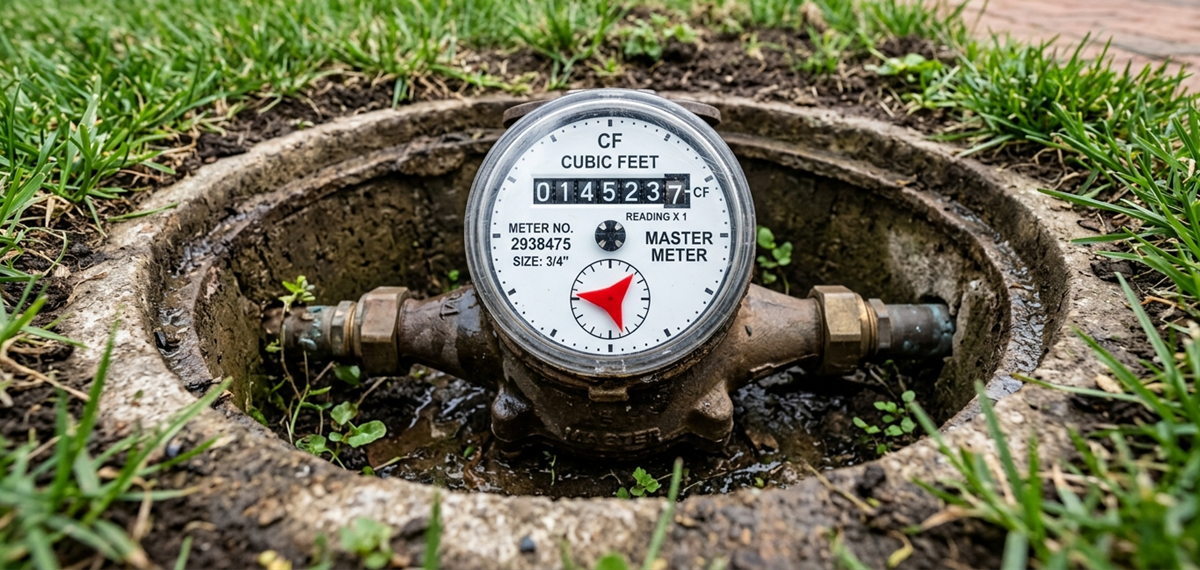
3. High-Altitude Cavitation: The Physics of Front Range Suction Flashing
Why does pump cavitation occur so easily in Broomfield?
Cavitation is not water hammer. It is the formation and violent implosion of vapor bubbles inside flowing liquid.
At sea level, water boils at 212°F under 14.7 PSI atmospheric pressure. But boiling is strictly a function of temperature and local absolute pressure. If you reduce the local pressure low enough, water will boil at room temperature (65°F).
The Net Positive Suction Head Equation
For a booster pump to operate without cavitation, the Net Positive Suction Head Available ($NPSH_a$) at the pump suction flange must exceed the pump manufacturer’s Net Positive Suction Head Required ($NPSH_r$):
We calculate $NPSH_a$ using the engineering formula:
Where:
- $h_{atm}$ = Atmospheric barometric pressure head (ft of absolute water)
- $h_s$ = Static suction pressure head at the pump inlet (ft)
- $h_f$ = Friction head losses through suction piping, strainer, and backflow preventer (ft)
- $h_{vp}$ = Vapor pressure head of the water at operating temperature (ft)
The 5,400-Foot Elevation Penalty
Here is why Front Range engineering matters:
- Sea Level Atmospheric Head ($h_{atm}$): $14.7\text{ PSI} \times 2.31 = 33.95\text{ ft of water}$
- Broomfield Atmospheric Head ($h_{atm}$ at 5,400 ft): $12.2\text{ PSI} \times 2.31 = 28.18\text{ ft of water}$
You lose nearly 6 feet of absolute suction head simply by standing in Broomfield.
When morning water demand surges and water velocity through an undersized suction header climbs to 10 feet per second, friction losses ($h_f$) spike. If static city pressure droops simultaneously, local absolute pressure at the suction impeller eye plunges below the water’s vapor pressure ($h_{vp}$).
Vapor pockets erupt in the water stream.
A microsecond later, those vapor bubbles travel into the higher-pressure region of the impeller vanes. They implode violently. Micro-jets of water shoot inward at velocities exceeding 1,000 meters per second, blasting microscopic pits into the 316 stainless steel impellers and vibrating the pump shaft violently.
That vibration rapidly destroys the mechanical seal faces.
4. VFD Hunting & Harmonic Destabilization
What makes a booster pump sound like it’s surging or revving up and down uncontrollably?
Modern booster systems rely on PID (Proportional-Integral-Derivative) control loops programmed into the variable frequency drives. A 4-20 milliamp pressure transducer on the discharge header measures real-time PSI and feeds data back to the VFD processor.
When PID parameters are improperly tuned or when an expansion tank loses its nitrogen pre-charge:
- A single commercial toilet flushes on floor 4. Discharge pressure drops by 2 PSI.
- The VFD over-reacts (excessive Proportional Gain $K_p$), instantly ramping the motor from 30 Hz to 60 Hz.
- Discharge pressure overshoots to 95 PSI.
- The VFD slams on the electronic brakes, dropping motor frequency to 20 Hz.
- Pressure collapses to 65 PSI. The cycle repeats every 4 seconds.
This phenomenon is known as VFD hunting.
Continuous acceleration and deceleration twists the pump shaft with severe torsional shock loads. Within months, mechanical seal springs fatigue, coupling inserts shear, and motor bearings develop electrical fluting from high-frequency shaft currents.
5. Shaft Voltage & Electrical Bearing Fluting
Few facility managers realize that the variable frequency drive controlling their booster pump can destroy mechanical seals from the inside out.
Modern VFDs use pulse-width modulation (PWM) with insulated-gate bipolar transistors (IGBTs) switching at carrier frequencies up to 16 kHz. This ultra-fast switching induces a parasitic capacitive voltage across the motor shaft.
When this common-mode shaft voltage exceeds the dielectric breakdown threshold of the motor bearing lubricant (typically 15 to 30 volts peak):
- An electrical discharge machining (EDM) spark arcs across the steel bearing balls.
- The microscopic electrical arc melts pits into the bearing raceway, creating washboard ridges known as bearing fluting.
- As bearing tolerances loosen, radial shaft runout increases from 0.001″ to over 0.006″.
- This radial wobble causes the mechanical seal faces to wobble axially at 3,500 RPM, allowing high-pressure water to squirt past the faces with every rotation.
Master plumbers prevent EDM destruction by installing circumferential micro-fiber shaft grounding rings (such as AEGIS SGR) on all inverter-duty booster motors.
6. Master Plumber Field Diagnostics: Step-by-Step Testing Protocol
When our commercial emergency technicians arrive at a failing booster skid in Broomfield, we systematically isolate and test every hydraulic parameter:
| Diagnostic Step | Instrument / Inspection Tool | Design Benchmark | Failure Symptom & Action Plan |
|---|---|---|---|
| 1. Suction & Discharge Differential | Calibrated Liquid-Filled Gauges | Suction ≥ 25 PSI; Discharge = 75 to 90 PSI steady |
Suction gauge fluttering violently between 5 and 20 PSI confirms severe suction cavitation. Clean suction Y-strainer screen immediately. |
| 2. Acoustic Ultrasonic Vibration | Ultrasonic Stethoscope / FFT Vibration Analyzer | Smooth laminar hum (< 2.5 mm/s RMS vibration velocity) | Loud crackling noise like popping bubble wrap confirms cavitation. Check NPSHa calculation and throttle discharge valve to move pump back on curve. |
| 3. Cartridge Seal Weep Rate | Visual Inspection of Lantern Drain Port | ≤ 3 drops per hour (normal vapor lubrication) | Steady stream or spraying mist confirms face fracture or O-ring blowout. Pull motor and install new pre-assembled cartridge seal kit. |
| 4. Expansion Tank Pre-Charge | Digital Tire Pressure Gauge on Schrader Valve | Pre-charge = Cut-in Setpoint minus 5 to 10 PSI | Water spraying from air valve confirms ruptured butyl bladder. Replace tank; lack of hydraulic cushioning causes rapid VFD hunting. |
| 5. VFD Ramp Time & PID Settings | Drive Programming Interface | Ramp-up: 3.0 to 5.0 sec; Ramp-down: 4.0 to 6.0 sec |
Ultra-fast 0.5-second ramp times cause water hammer and shaft torsion. Smooth acceleration curves to protect mechanical couplings. |
7. How to Replace a Cartridge Mechanical Seal in the Field
Replacing a multi-stage pump seal no longer requires tearing down the entire 12-stage impeller stack. Master plumbers follow a precise cartridge replacement protocol:
- Isolate and De-pressurize: Close suction and discharge butterfly isolation valves. Lockout/tagout the 480V circuit breaker. Open the casing drain plug to vent all hydrostatic pressure.
- Remove Motor Coupling: Unbolt the two-piece aluminum or cast iron shaft coupling guards. Remove the axial coupling bolts. Note the exact shaft height position using a digital vernier caliper.
- Loosen Shaft Set Screws: Loosen the radial set screws locking the seal sleeve to the pump shaft.
- Extract Cartridge Gland: Unbolt the four gland bolts holding the seal plate to the pump head. Slide the old cartridge seal assembly upward off the shaft.
- Inspect Shaft Surface: Clean the stainless steel shaft with Scotch-Brite. Check for fretting, scoring, or runout. Shaft runout must measure under **0.002 inches TIR (Total Indicator Reading)** on a dial indicator.
- Install New Seal & Engage Locking Tabs: Slide the new pre-assembled cartridge seal down over the shaft, torque gland bolts to factory specs, tighten shaft set screws, and pull the plastic centering/locking clips before rotating the shaft by hand.
8. Hydraulic Pipe Sizing: Suction Header Reynolds Numbers & Turbulence
Why do booster pumps cavitate even when city pressure reads 40 PSI at rest?
The secret lies in the velocity and turbulence inside the suction manifold.
Under the Hydraulic Institute Standards (ANSI/HI 9.6.6), fluid velocity entering a multi-stage centrifugal pump suction header must not exceed 4.0 to 5.0 feet per second.
Crucially, a straight run of pipe equal to at least **five pipe diameters ($5D$)** must be provided between any elbow, reducer, or butterfly valve and the pump suction flange.
When contractors crowd a mechanical room and place an eccentric reducer or 90-degree elbow directly on the pump suction flange:
- The flow separates along the outer elbow radius.
- A localized vortex forms inside the suction eye.
- The Reynolds number ($Re = \frac{\rho v D}{\mu}$) spikes into severe turbulence ($Re > 100,000$).
- The uneven velocity distribution starves one side of the first-stage impeller, inducing asymmetric cavitation and rapid mechanical seal failure.
9. Real-World Case Study: 10-Story Broomfield Residential Tower Rescue
In December 2025, our master plumbing emergency dispatch received a priority call from a 120-unit luxury residential high-rise in Broomfield. Tenants on floors 8 through 10 had zero water pressure during the 7:00 AM morning shower rush, while the basement mechanical room had three inches of standing water.
Here is what our forensic inspection uncovered:
- The Failure: Lead Pump 1 had blown its silicon carbide seal cartridge. Water was spraying at 90 PSI directly onto the VFD panel heatsinks. Pump 2 was locked out on inverter overcurrent. Pump 3 was vibrating violently with a roaring gravel sound.
- The Root Cause: The building’s 120-gallon ASME expansion tank had blown its internal butyl bladder, completely waterlogging the tank. Without an air cushion, the VFD PID loop was hunting every 2 seconds, cycling the pumps between 15 Hz and 60 Hz hundreds of times an hour. The pressure surges fractured the brittle silicon carbide seal faces.
- The Repair: We isolated the skid, installed an emergency Grundfos cartridge seal kit, replaced the waterlogged expansion tank with an ASME-certified 150 PSI pre-charged bladder tank, recalibrated the VFD PID loop integral gain, and restored full 85 PSI domestic water pressure to the penthouse within four hours.
10. Expansion Tank Pre-Charge Calculation & Sizing Equations
A booster skid cannot function stably without a properly sized hydropneumatic expansion tank.
To determine required acceptance volume ($V_1$) for a commercial booster package:
Where pressures are expressed in PSIG and 12.2 represents absolute atmospheric pressure head at Broomfield’s 5,400-foot elevation.
Crucial Rule of Pre-Charge: The nitrogen bladder pre-charge pressure must always be calibrated with the water side hydrostatically drained to 0 PSI. Setting the pre-charge while line water pressure is applied results in false readings and rapid bladder rupture.
11. Preventive Maintenance Checklist: Keeping High-Rise Water Flowing
To prevent a sudden loss of building domestic water pressure, implement this maintenance schedule:
- Monthly Strainer Blowdown: Open the blowdown ball valve on the primary suction Y-strainer for 15 seconds under flow to clear accumulated rust flakes and municipal pipe scale.
- Quarterly Lead/Lag Rotation Audit: Verify through the digital controller that the lead pump alternates automatically every 24 operating hours to distribute mechanical seal runtime evenly across all three pumps.
- Semi-Annual Expansion Tank Bladder Inspection: Check air pre-charge pressure with the pump skid isolated and hydrostatically drained. Maintain nitrogen charge within 5 PSI of target.
- Annual Infrared Thermography: Scan pump motor bearings, shaft couplings, and drive contactor terminals for abnormal thermal rise indicating bearing failure or shaft misalignment.
- Annual Vibration FFT Analysis: Measure radial and axial vibration velocities across all bearing housings to detect early-stage impeller cavitation erosion before seal blowouts occur.
12. The Pump Affinity Laws: Energy & Hydraulic Calculations under VFD Control
How does reducing motor frequency save energy while altering booster pump head?
Variable frequency drives manipulate motor synchronous speed ($N$) by altering line AC frequency ($f$). The physical behavior of a vertical multi-stage centrifugal pump obeys the fundamental Pump Affinity Laws:
$$\text{Head Pressure: } \frac{H_1}{H_2} = \left(\frac{N_1}{N_2}\right)^2$$
$$\text{Brake Horsepower: } \frac{BHP_1}{BHP_2} = \left(\frac{N_1}{N_2}\right)^3$$
Notice the exponential cubic relationship for motor power ($BHP$). If a booster pump motor slows from 60 Hz down to 50 Hz (an approximate 17% reduction in speed):
Power consumption plummets by 42%.
However, look closely at the second affinity equation: pump head collapses by the square of speed ($\Delta H \propto N^2$). If the drive slows down too much, the pump reaches its zero-flow cutoff head.
The spinning impellers can no longer generate enough hydraulic lift to overcome static building elevation. The pump dead-heads inside its own casing, churning trapped water into boiling steam in under six minutes. To prevent this, master plumbers program a hard minimum speed cutoff (typically 25 to 30 Hz) into the VFD firmware, automatically placing the pump into sleep mode whenever demand ceases.
13. ASME Section IV Pressure Relief Valve Sizing on Booster Headers
What protects the commercial domestic water piping from bursting if the VFD processor locks up at 60 Hz?
Under the International Plumbing Code (IPC Section 604.8) and ASME Section IV standards, every commercial booster package must incorporate an independent, pilot-operated or spring-loaded high-pressure relief valve piped directly to a floor sink or mechanical room drain.
If a shorted VFD transistor drives the lead pump to maximum speed while all fixtures in the building are closed:
- Municipal suction pressure (50 PSI) adds directly to maximum pump cutoff head (e.g., 90 PSI).
- Discharge manifold pressure surges to 140 PSI.
- Standard commercial copper fittings, PEX tubing, and commercial toilet flushometer diaphragms are rated for a continuous maximum operating pressure of 80 PSI per IPC 604.8.
The ASME-rated relief valve must be sized to discharge at least 100% of maximum pump design capacity ($Q_{\text{max}}$) without allowing manifold pressure to exceed 10% above the relief setpoint (typically set at 95 to 100 PSI). Pinhole relief valves are illegal; commercial discharge lines must be full-size (typically 1-1/2″ to 2-1/2″ copper or flanged steel) with an air-gap drain fitting to prevent back-siphonage.
14. Backflow Prevention & Cross-Connection Hazards: RPZ vs. Air Gaps
A powerful booster pump can pull high-volume water from municipal street mains.
If municipal main pressure drops unexpectedly due to a fire truck pumping a nearby hydrant or an underground street main rupture, a running booster pump can create a powerful negative vacuum in the utility service lateral.
This negative pressure can suck non-potable water, boiler chemicals, or contaminated irrigation runoff backward into the municipal drinking water supply.
To satisfy Colorado Department of Public Health and Environment (CDPHE) Regulation 11, master plumbers install one of two cross-connection barrier systems upstream of commercial booster skids:
- Reduced Pressure Zone (RPZ) Backflow Assemblies (ASSE 1013): Incorporates two independent spring-loaded check valves separated by an intermediate differential relief valve. If upstream pressure drops or downstream pressure reverses, the relief valve dumps water to the drain, venting the zone to atmospheric pressure. RPZ valves must be tested and certified annually by a licensed Colorado ASSE tester.
- Break Tanks with Atmospheric Air Gaps: For critical medical, pharmaceutical, or high-hazard commercial facilities, municipal water discharges into an unpressurized stainless steel break tank through a physical air gap twice the diameter of the supply pipe. The booster pumps pull strictly from the break tank, creating an absolute physical disconnect between the building plumbing and the city water grid.
All backflow testing results must be entered into the municipal water purveyor compliance database (such as XC2 software) within thirty calendar days of testing. Failure to record annual certification will result in municipal water shutoff enforcement actions.
Frequently Asked Questions About Commercial Water Booster Pumps
Why is my domestic water booster pump making a loud rattling sound like stones inside?
That sound is the hallmark sign of hydraulic cavitation. Vapor bubbles formed at the low-pressure suction eye are violently collapsing against the impeller blades. This occurs when suction pressure drops too low, the suction strainer is clogged, or the pump is operating far past its designed flow rate.
Can you run a commercial booster pump while the mechanical seal is dripping water?
A few drops per hour is normal lubrication weeping for certain seal faces, but a steady trickle or spray indicates the seal faces are fractured or grooved. Running a leaking pump risks spraying water directly into the motor lower bearing, causing electrical short-circuits and catastrophic motor burnout.
What causes variable frequency drives (VFDs) on booster pumps to hunt and surge?
VFD hunting is typically caused by waterlogged expansion tanks with blown bladders, an overly aggressive PID proportional gain setting in the controller, or a sluggish/partially clogged pressure transducer sensing line that feeds delayed pressure signals to the drive.
Why does elevation affect water booster pump performance in Broomfield, CO?
At Broomfield’s 5,400-foot elevation, atmospheric pressure is roughly 12.2 PSI compared to 14.7 PSI at sea level. This nearly 6-foot reduction in Net Positive Suction Head Available (NPSHa) dramatically increases the risk of water boiling into cavitation bubbles at lower suction pressures.
Who handles emergency commercial booster pump rebuilds in Broomfield, Colorado?
Broomfield Emergency Plumber provides 24/7 commercial booster pump and VFD skid emergency repair across Broomfield and the Front Range. Call our master plumbers immediately at (303) 647-3363 for emergency seal replacements, cavitation troubleshooting, and motor rebuilds.
Commercial Booster Pump Leaking or Losing Building Water Pressure?
Don’t let mechanical seal blowouts or cavitation damage leave your high-rise building or commercial tenants without domestic water. Our certified commercial technicians provide 24/7 emergency booster skid diagnostics, cartridge seal replacements, and VFD tuning across Broomfield and the Denver metro area.
Call (303) 647-3363 for Immediate Commercial Booster Service
Commercial Sewage Grinder Pump High-Water Alarm & Shredder Jam: Radial Cutter Clearances, Thermal Overload Tripping & Dual-Basin Alternation
Down in the lower mechanical room of a busy Broomfield medical office building or multi-tenant commercial plaza, an amber strobe light flashes frantically on the wall. A piercing 90-decibel horn echoes through the basement corridors. The digital control panel on the duplex lift station flashes red: ALARM: HIGH WATER LEVEL — PUMP 1 OVERLOAD TRIP — PUMP 2 RUNNING CONTINUOUS. Over by the sealed cast-iron basin cover, raw sewage is backing up inside the floor drains, threatening thousands of dollars of server racks, medical records, and finished drywall.
Your sewage grinder pump system is jammed.
Don’t ignore the high-water horn or simply press “Silence” and walk away.
When a commercial grinder pump stops grinding, raw municipal solids and wastewater don’t magically disappear. Every flush from the floors above adds dynamic head to an already overflowing wet well. Within thirty minutes, contaminated blackwater will breach floor drains and basement toilet bowls.
Commercial sewage grinder pumps are high-torque industrial machines designed to pulverize sanitary solids into a slurry and pump them uphill against steep dynamic head pressures. But when industrial rags, non-woven polypropylene “flushable” wipes, dental floss nests, or construction debris wedge between the high-chrome cutter teeth, the motor pulls locked-rotor amps (LRA) in milliseconds. Thermal overloads trip.
Let’s examine the mechanical physics of commercial grinder pumps, dissect radial cutter clearance tolerances, troubleshoot float switch grease blinding, and review master plumber emergency rebuild and panel diagnostic protocols.

1. Grinder Pump Anatomy: Cutter Discs, Shredder Rings & Hydraulic Impellers
How does a commercial grinder pump differ from a standard residential sewage ejector?
A traditional sewage ejector uses a semi-open vortex impeller to pass solid spherical objects up to 2 inches in diameter through large 2″ or 3″ discharge piping. Ejectors don’t chop solids; they simply swirl them through the volute.
A commercial grinder pump operates under a completely different hydraulic philosophy. Grinder pumps are engineered to tackle high dynamic heads (often 50 to 130+ feet of vertical lift) through smaller 1-1/4″ to 2″ pressurized force mains. To prevent smaller force mains from plugging, the pump must pulverize everything into a fine, liquid slurry before the fluid enters the impeller eye.
The Two-Stage Cutting Mechanism
At the bottom of the submersible pump volute sits a hardened cutting assembly crafted from 440C stainless steel or Rockwell C 58-60 hardened high-chrome alloy:
- The Stationary Cutter Ring (Shredder Ring): Bolted solidly to the pump suction inlet. It features a perimeter of machined, razor-sharp shearing slots and internal cutting edges.
- The Rotating Cutter Blade (Impeller Cutter): Mounted directly to the hardened stainless steel motor shaft, spinning at either **1,750 RPM or 3,450 RPM**. As it rotates, it sweeps past the stationary ring with scissor-like shearing action, delivering tens of thousands of cutting strokes per minute.
The Critical .008″ Cutter Clearance
For a grinder pump to shred synthetic wipes, feminine hygiene products, and latex gloves without jamming, the mechanical gap between the spinning cutter and stationary shredder ring must remain microscopic:
Think about that clearance. Eight-thousandths of an inch is barely thicker than two sheets of notebook paper.
When sand, abrasive grit, or construction grout passes through the cutter, the hardened cutting edges round off. Worse yet, if fine textile fibers wedge into the gap, they deflect the cutter blade axially. The gap expands from 0.008″ to 0.020″.
Once clearance opens up, the pump stops cutting. Fibers stop shearing and begin wrapping tightly around the rotating shaft like a winch cable. The cutter binds against the stationary ring.
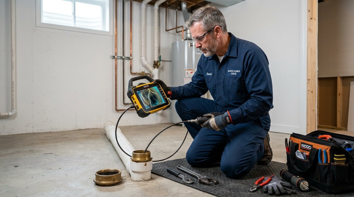
2. Electrical Diagnostics: Locked-Rotor Amperage (LRA) & Thermal Lockout
What happens electrically when a shredder jams?
Electric induction motors draw a specific full-load amperage (FLA) when pumping liquid under standard design conditions. But when the cutter mechanism suddenly binds solid, the motor rotor is instantly locked in place while full line voltage remains applied across the stator windings.
In that instant, the motor draws **Locked-Rotor Amps (LRA)**:
| Motor Rating | Supply Voltage & Phase | Normal Full Load Amps (FLA) | Locked Rotor Amps (LRA) | Time to Thermal Overload Trip |
|---|---|---|---|---|
| 2.0 HP Grinder | 208V / 1-Phase | 13.5 A | 68.0 A | 3 to 7 Seconds |
| 2.0 HP Grinder | 240V / 1-Phase | 12.0 A | 60.0 A | 3 to 7 Seconds |
| 3.0 HP Grinder | 208V / 3-Phase | 9.8 A | 54.0 A | 4 to 8 Seconds |
| 5.0 HP Grinder | 480V / 3-Phase | 7.6 A | 45.0 A | 3 to 6 Seconds |
When 60+ amps course through copper motor windings rated for 12 amps, resistance heating ($I^2 R$) generates extreme temperatures. In less than eight seconds, winding temperatures climb toward 300°F.
To prevent the motor from bursting into flames inside the oil-filled housing, the manufacturer builds in an internal thermal overload switch or wires an external bimetallic thermal protector into the control panel circuit. The overload contacts snap open, de-energizing the motor magnetic contactor.
The pump goes dead. The alarm illuminates.
3. Single-Stage vs. Two-Stage Grinder Mechanisms
In commercial wastewater engineering, pumps utilize distinct cutter architectures tailored to the anticipated solid waste stream:
| Feature | Radial Cutter Design (e.g., Barnes Razor / Myers VR) | Axial Cutter Design (e.g., Flygt M3000 / Zoeller Shark) |
|---|---|---|
| Cutter Motion | Spinning horizontal disc sweeping past radial shear slots. | Heavy conical rotating head with spiral teeth boring into stationary cutter ring. |
| Cutting Force | High-speed shearing scissor action (3,450 RPM). | Crushing and masticating axial extrusion action (1,750 or 3,450 RPM). |
| Tolerance to Non-Woven Textiles | Exceptional when clearance is strictly maintained at 0.008″. | Better at passing heavy plastics, clothing fragments, and rubber gloves. |
| Wear Adjustment | Shims behind rotating cutter blade. Requires feeler gauge. | Axial adjustment screw on bottom casing without pump teardown. |
4. Duplex Control Panel Anatomy: Alternators, Capacitors & Float Failures
Commercial facilities almost never rely on a single grinder pump. The International Plumbing Code (IPC Section 712.4.2) requires commercial lift stations receiving waste from six or more plumbing fixtures to incorporate a duplex pump arrangement.
How the Duplex Brain Functions
Inside the NEMA 4X fiberglass control panel enclosure, an electronic alternator logic board coordinates the two pumps:
- Cycle 1: Pump 1 starts, empties the basin down to the “Stop” level, and turns off.
- Cycle 2: Next inflow cycle, the alternator flips. Pump 2 starts, empties the basin, and turns off.
- High Inflow / Jam Condition: If Pump 1 is running but cannot keep up (or if Pump 1 tripped on thermal overload), the liquid continues to rise until it triggers the “Lag / High-Water” float switch. The panel immediately energizes Pump 2 to assist, while latching the visual and audible emergency alarm circuits.
The Enemy: Grease Crust & Float Blinding
Why do float switches fail along the Colorado Front Range?
Commercial wastewater contains animal fats, vegetable oils, and synthetic soap curds. Over months of operation, this grease emulsifies, floats to the surface of the wet well, and cools into a dense, buoyant crust resembling hardened tallow.
Suspended mechanical float switches become encrusted in this grease cake:
- Float Weighed Down: A 10-pound mass of grease clings to the “Start” float, preventing its internal steel ball from rolling across the electrical contacts when water rises. The pump never receives the signal to turn on.
- Float Glued in the Up Position: Grease wedges the “Stop” float against the basin wall, holding it tipped upward. The grinder pump continues running dry long after the basin is pumped empty. Submersible pumps rely on wastewater for motor cooling; run a dry grinder pump for fifteen minutes, and the mechanical silicon-carbide shaft seals shatter from thermal shock.
5. Cold Weather Lift Station Hazards: Frozen Force Mains
In Broomfield and across the Denver metro area, our winter frost line extends to **36 to 42 inches below grade**.
When a grinder pump discharges into an exterior force main running under an uninsulated parking lot or through an unheated retaining wall, standing water in the discharge riser will freeze solid overnight if the check valve fails or if the line was graded without proper continuous drainage slope.
If the discharge pipe freezes solid with ice, the grinder pump turns on against a dead-headed hydraulic block. The spinning impeller churns the same three gallons of water trapped in the volute. In minutes, that trapped water boils into steam, melting the PVC discharge piping, de-tempering the cutting blades, and frying the pump stator.
6. Master Plumber Emergency Diagnostics: Step-by-Step Restoration Protocol
When our commercial emergency trucks arrive at a flashing lift station alarm, we execute a rigorous forensic restoration sequence:
| Diagnostic Sequence | Field Test Procedure | Normal Tolerance | Emergency Action if Out of Spec |
|---|---|---|---|
| 1. Lockout / Tagout (LOTO) | Disconnect primary 208V/240V/480V three-phase disconnect at the panel. | Zero voltage verified with Fluke CAT-IV multimeter. | Never insert hands or tools into a grinder basin without physical mechanical disconnect and LOTO lock applied. |
| 2. Motor Winding Resistance | Measure resistance across T1-T2, T2-T3, T1-T3 with digital ohmmeter. | Balanced resistance within ±3% across all three phases (typically 1.5 to 8.0 Ω). | Infinite resistance (∞) indicates open winding. Zero resistance indicates shorted coil. Pull pump for full stator rewind or replacement. |
| 3. Megohmmeter (Megger) Insulation Test | Apply 500V or 1,000V DC between motor leads and ground wire. | > 20 Megaohms (MΩ) for installed pumps; > 100 MΩ for new. | Reading below 1.0 MΩ confirms water ingress past the mechanical shaft seal into the oil chamber. Overhaul required. |
| 4. Mechanical Jam Extraction | Fit a hardened spanner wrench or hex drive to the external shaft cutter bolt. Manually rotate counter-clockwise. | Smooth, free 360-degree rotation with light hand torque. | If seized solid, extract foreign debris (textiles, cable ties, mop strings) with heavy needle-nose pliers. Reset cutter clearance to 0.008″. |
| 5. Float Switch Tilt Verification | Manually lift floats one by one with an insulated fiberglass reach rod. | Audible click inside float; control panel relay clicks; pump contactor pulls in immediately. | Scrape grease cake using hot-water pressure wash. Replace failed mechanical microswitches with sealed transducer or optical sensors. |
7. Sizing Calculations: Total Dynamic Head (TDH) & Hazen-Williams Losses
A frequent cause of premature grinder pump failure is hydraulic misapplication: installing a pump that operates off the right-hand end of its pump curve where motor amperage runs continuously high.
To ensure the replacement pump operates inside its hydraulic sweet spot, calculate Total Dynamic Head ($TDH$):
Where:
- $H_{\text{static}}$ = Vertical elevation difference from basin bottom to highest discharge point (ft)
- $H_{\text{friction}}$ = Pipe wall friction loss calculated via Hazen-Williams formula:
$$h_f = 0.2083 \times \left(\frac{100}{C}\right)^{1.852} \times \frac{Q^{1.852}}{d^{4.8655}} \times L$$ - $H_{\text{fittings}}$ = Equivalent pipe length losses through check valves, 90° elbows, and gate valves (ft)
- $P_{\text{residual}}$ = Pressure required to discharge into pressurized city force main (ft of head = PSI × 2.31)
If a facility has 38 feet of static lift and 18 feet of friction loss across 350 feet of 2″ schedule 40 PVC ($TDH = 56\text{ ft}$), installing a pump rated for a maximum cutoff head of 50 feet will result in continuous zero-flow operation, severe overheating, and instant motor burnout.
8. Confined Space Safety: OSHA & NFPA 820 Wastewater Regulations
Entering a commercial sewage wet well is classified under OSHA Standard 1910.146 as a Permit-Required Confined Space.
Anaerobic decomposition inside commercial sewage pits generates lethal atmospheric hazards:
- Hydrogen Sulfide ($H_2S$): Heavier than air. Paralyzes olfactory nerves at 100 PPM. Lethal at 300 PPM in minutes.
- Methane ($CH_4$): Highly explosive hydrocarbon gas with a Lower Explosive Limit (LEL) of 5%.
- Oxygen Depletion ($O_2$): Bacterial consumption drives ambient oxygen levels below 19.5%, causing sudden asphyxiation.
Our commercial crews utilize calibrated 4-gas atmospheric monitors, forced mechanical ventilation blowers (minimum 2,000 CFM), full-body harness retrieval tripods, and explosion-proof non-sparking hand tools meeting NFPA 820 Class 1, Division 1 electrical classifications. Never enter a sewage wet well without certified confined-space safety protocols.
9. Real-World Case Study: Broomfield Office Plaza Basement Flooding Averted
In January 2026, an alarm sounded at 6:15 AM at a commercial professional center on 120th Avenue in Broomfield. The lower-level accounting firm was thirty minutes from opening, and their floor sinks were gurgling contaminated wastewater.
Our emergency commercial truck arrived within 25 minutes. Here is what we found:
- Control Panel State: Pump 1 thermal overload tripped. Pump 2 starter contactor chattering rapidly due to pitted silver contacts. Wet well water level stood three inches below the electrical conduit entry.
- Pump Extraction: We hoisted Pump 1 using the stainless steel guide rail crane. The cutter teeth were choked with an 8-inch solid rope of microfiber mop strands and synthetic disinfectant wipes flushed by the night janitorial crew.
- Field Rebuild: We torqued the shaft reverse bolt, extracted the bound textile nest, measured cutter gap at 0.019″ (nearly double tolerance), removed two brass adjustment shims to restore clearance to 0.008″, and meggered the motor at 85 Megaohms (healthy stator insulation).
- Restoration: We replaced the chattering control panel contactor, steam-cleaned the blinded float switches, and ran three automated alternation pump cycles. The wet well emptied cleanly in 42 seconds per cycle. Zero water escaped onto the carpet.
10. Guide-Rail Disconnect Systems: Why Manual Basin Entry is Obsolete
In modern commercial architecture, nobody should ever have to unbolt a pump at the bottom of a wastewater pit.
The International Plumbing Code and best trade practices dictate dual-pipe guide rail quick-disconnect systems:
- Cast Iron Discharge Foot: Bolted permanently to the concrete basin floor and connected to the discharge force main.
- Mating Slide Flange: Bolted to the pump discharge neck with an integrated NBR or Viton seal face.
- Stainless Steel Guide Pipes: Two vertical 304 or 316 stainless steel pipes extend from the discharge foot up to the access hatch.
When the pump is lowered on a stainless lifting chain, gravity guides the slide flange down the rails until it mates tightly against the discharge foot. Hydrostatic discharge pressure locks the elastomeric seal bubble-tight. When service is required, the pump is hoisted straight up to ground level without loosening a single bolt inside the pit.
11. Preventive Maintenance Checklist: Keeping Grinder Systems Jam-Free
To prevent a sudden loss of building drainage and costly blackwater cleanups:
- Monthly Float Visual Inspection: Check float switch freedom. Wash away grease buildup with hot water wand.
- Quarterly Current Draw Logging: Record running amperage of both pumps under full load. Any rise above 10% of FLA indicates cutter dulling or hydraulic restriction.
- Semi-Annual Oil Chamber Check: Drain sample plug on pump motor housing. Clear oil indicates healthy seals. Milky or cloudy oil indicates water emulsion and requires immediate mechanical seal renewal.
- Annual Feeler Gauge Recalibration: Hoist pumps to surface. Inspect cutting edges under 10x magnification. Reset clearance to 0.008″ using factory shims.
12. Commercial Lease Language & Tenant Plumbing Rules
The most engineered grinder pump in the world will fail if occupants treat toilets like trash cans.
We strongly advise commercial building landlords to insert explicit wastewater rider clauses into tenant lease agreements:
“Tenants shall strictly prohibit the disposal of non-flushable sanitary wipes, paper towels, dental floss, mop strands, latex gloves, and grease into plumbing fixtures. Any pump jam or wet well overflow directly traced to prohibited tenant waste shall be billed 100% to the offending tenant’s common area maintenance (CAM) account.”
Posting clear, laminated instructional signage in commercial restrooms reduces wipe-induced grinder jams by over 75% overnight.
13. Wet Well Hydraulic Sizing Math: Cycle Frequency & Retention Margins
Why do commercial grinder wet wells overflow so rapidly during peak usage?
In commercial buildings, basin volume cannot simply be guessed. Wet wells must be sized according to peak fixture units and allowable motor starts per hour. Submersible motor manufacturers strictly specify a maximum of **10 to 12 starts per hour** to prevent thermal degradation of motor insulation.
To determine minimum active liquid storage volume ($V_{\text{active}}$) in gallons between the “Pump Stop” and “Pump Start” float levels:
Where:
- $T_{\text{cycle}}$ = Minimum allowable cycle time in minutes ($T_{\text{cycle}} = \frac{60\text{ min}}{\text{Max Starts/hr}} = \frac{60}{10} = 6\text{ minutes}$)
- $Q_{\text{pump}}$ = Rated flow rate of a single grinder pump in GPM (e.g., 40 GPM at 60 ft TDH)
Across a standard 36-inch diameter cylindrical fiberglass basin, one vertical inch of depth contains:
To achieve 60 gallons of active storage, the vertical differential between the “Stop” and “Lead Start” float must measure at least **13.6 inches**. If an inexperienced contractor hangs the floats only 4 inches apart, the pump will cycle every 90 seconds, pulling heavy inrush current 40 times per hour until the thermal protector permanently welds shut.
14. Soft Starters vs. Across-The-Line Contactor Dynamics
When a 3-horsepower or 5-horsepower grinder pump kicks on, the electrical and mechanical systems experience a violent jolt.
In traditional Across-the-Line (DOL) starters, full supply line voltage (208V, 240V, or 480V) is slammed across the motor stator in zero milliseconds. The motor produces an explosive torque surge:
- Mechanical shock twists the pump volute on its guide rail base.
- Starting current spikes to 600% of full-load amperage, dimming lights across the facility.
- Internal radial cutter teeth slap against solids with violent impact, increasing risk of tooth chipping.
In modern Front Range commercial facilities, master plumbers upgrade control panels with Solid-State Soft Starters (SSMS). Soft starters use silicon-controlled rectifiers (SCRs) to ramp motor voltage smoothly over 1.5 to 2.5 seconds:
- Starting current is clamped to a manageable 250% to 300% of FLA.
- Torsional stress on the stainless steel motor shaft is reduced by over 70%.
- The radial cutter blade accelerates smoothly into the waste stream, slicing through wipes without torque spikes that cause false thermal overload trips.
15. Check Valve Slap, Water Hammer & Force Main Anti-Air-Lock Physics
What causes the terrifying metallic clang heard every time a sewage grinder pump stops?
When the pump de-energizes, the column of wastewater in the vertical force main abruptly reverses direction under gravity, slamming the heavy swing check valve disc into its brass or cast iron seat. This is check valve slam.
To protect piping from fatigue cracks:
- Install Resilient-Hinged Ball Check Valves: Replace rigid swing flappers with vulcanized rubber ball check valves. The rubber-encapsulated hollow ball is pushed upward during flow and sinks softly into a conical elastomer seat when flow ceases, eliminating 95% of hydraulic shock.
- Drill the 3/16″ Anti-Airlock Relief Hole: The International Plumbing Code requires a 3/16-inch weep hole drilled into the discharge pipe between the pump volute outlet and the check valve. When the wet well is pumped down, trapped air can compress under the check valve, preventing water from reaching the impeller eye during the next cycle (air-locking). The 3/16″ hole allows trapped air to vent freely into the basin, guaranteeing instant hydraulic prime.
16. Emergency Backup Power & Generator Load Step Sizing
What happens to your below-grade lift station when a violent Front Range winter storm knocks out commercial utility power across Broomfield?
Plumbing fixtures on the upper floors of an office tower or medical center will continue to be flushed by occupants during a blackout. If the duplex grinder lift station does not transfer seamlessly to emergency standby power, the wet well will fill and overflow within forty-five minutes.
Under NFPA 110 (Standard for Emergency and Standby Power Systems) and commercial building codes, lift station circuits connected to automatic transfer switches (ATS) must be engineered for motor locked-rotor starting kVA:
- Starting kVA Sizing: A 3 HP 208V single-phase grinder pump requires roughly 3.5 kW of running power, but demands over 14 kVA of instantaneous starting capacity. If the emergency generator is undersized, the starting voltage dip will exceed 20%, causing the ATS contactors to chatter or drop out.
- Staggered Restart Logic: Duplex control panels connected to backup generators must incorporate time-delay relays (typically 10 to 15 seconds) preventing both grinder pumps from attempting to start simultaneously when generator power first energizes the bus.
Frequently Asked Questions About Commercial Sewage Grinder Pumps
Why is my commercial grinder pump running continuously without shutting off?
A continuously running pump is usually caused by one of three issues: a stuck or grease-weighted ‘Stop’ float switch holding the circuit closed, a severe mechanical cutter jam that sheared the drive key (motor spins but cutter doesn’t turn), or a clogged discharge check valve that prevents wastewater from leaving the basin.
Can you flush ‘flushable wipes’ into a commercial grinder pump system?
Absolutely not. So-called ‘flushable’ wipes are composed of woven synthetic polyester and polypropylene fibers that do not break down in water. In commercial high-volume environments, these fibers twist into dense ropes that wedge into the 0.008\” cutter gap, seizing the motor and causing thermal overload trips.
What does it mean when the lift station high-water alarm sounds?
It means the liquid level inside the wet well has risen past the normal operating pump-start level and triggered the emergency high-water float. This signals that neither pump is operating, the pumps are failing to keep up with inflow, or the discharge force main is blocked.
How long can a commercial building operate once a grinder pump fails?
Very briefly. Depending on wet well basin volume and building occupancy, an un-pumped commercial basin typically fills to overflowing within 20 to 45 minutes of active plumbing fixture use. Fixture usage must be halted immediately until service arrives.
Who provides 24/7 commercial sewage grinder pump repair in Broomfield, Colorado?
Broomfield Emergency Plumber provides 24/7 commercial lift station and grinder pump emergency dispatch across Broomfield, Boulder, and the Denver metro area. Call our master plumbers immediately at (303) 647-3363 for pump pulls, cutter rebuilds, and control panel diagnostics.
Sewage Grinder Alarm Sounding or Lift Station Backing Up?
Don’t let a sewage pump failure flood your commercial property with hazardous blackwater. Our master commercial plumbers carry heavy-duty replacement grinder pumps, control panel components, and guide-rail hoists ready for immediate 24/7 dispatch.
Call (303) 647-3363 for 24/7 Emergency Grinder Pump Dispatch
Commercial Gas Pressure Regulator Vent Leaking & Diaphragm Rupture: Vent Limiter Failures, IFGC Section 410 & High-Lockup Spikes
You step into the boiler room or behind the commercial kitchen cook line on a freezing Colorado morning, and a sharp, rotten-egg sulfur stench stops you dead in your tracks. High above the gas distribution header, a metallic hissing echoes off the concrete masonry. You trace the sound to an industrial appliance regulator mounted upstream of the heavy commercial fryers and pizza ovens. Soap bubbles brushed onto the threaded atmospheric vent port immediately froth into an aggressive, boiling dome of foam. Raw natural gas is blowing straight into the occupied building envelope.
Don’t touch electrical switches. Don’t fumble with digital thermostats.
Kill the primary gas isolation ball valve immediately. Evacuate the kitchen.
What just happened?
A reinforced elastomeric diaphragm inside the gas pressure regulator tore along its perimeter bead. Under the International Fuel Gas Code (IFGC Section 410) and NFPA 54, an appliance regulator diaphragm separates high incoming delivery pressure from the ambient room atmosphere. The moment that internal rubber membrane ruptures, line pressure charges the atmospheric upper chamber. If the internal vent limiter ball check fails to seat, or if the atmospheric vent was never piped to the building exterior, you have an explosive fuel-air mixture accumulating inside your facility.
Here along the Colorado Front Range, our 5,400-foot altitude and violent winter temperature swings push commercial fuel gas assemblies to their mechanical limits. Let’s dissect the engineering anatomy of commercial regulator diaphragm ruptures, lockup pressure spikes, vent limiter physics, IFGC venting compliance, and step-by-step master plumber emergency response protocols.
1. Gas Pressure Physics: The Three-Pressure Cascade in Commercial Facilities
A commercial gas distribution system does not operate at a single uniform pressure. It is an engineered pressure cascade designed to move high BTU volumes through modest pipe diameters before stepping down to delicate appliance burner limits.
In the City and County of Broomfield, utility providers like Xcel Energy deliver natural gas from the street main into commercial utility meters at three distinct delivery classes:
- Standard Low-Pressure Utility Delivery: 7.0″ to 14.0″ Water Column (approx. 0.25 to 0.50 PSI). Found in older light-commercial strip centers built prior to 1990.
- Medium-Pressure Utility Delivery (Elevated Delivery): 2.0 PSI (55.4″ Water Column). The modern standard for commercial kitchens, multi-family central boiler plants, and retail centers. Moving gas at 2 PSI allows plumbers to use 1-1/4″ or 1-1/2″ supply risers instead of bulky 3″ or 4″ low-pressure headers, saving tremendous structural space and piping installation costs.
- High-Pressure Industrial Delivery: 5.0 to 10.0+ PSI. Reserved for heavy manufacturing campuses, commercial asphalt batch plants, and large district campus heating boilers.
Commercial cooking equipment, gas-fired hydronic boilers, unit heaters, and domestic water heaters cannot tolerate 2 PSI. Standard commercial appliances operate on low manifold pressure:
- Natural Gas Appliance Manifolds: 3.5″ to 5.0″ Water Column (0.12 to 0.18 PSI).
- Propane (LP) Appliance Manifolds: 10.0″ to 11.0″ Water Column (0.36 to 0.40 PSI).
If 2 PSI (55″ WC) surges past a failing regulator and hits a commercial gas fryer combination control valve rated for a maximum inlet pressure of 1/2 PSI (14″ WC), the internal safety shutoff solenoid blows out, internal diaphragm gaskets tear, and uncontrolled raw gas sprays past the burner orifices.
2. Mechanical Anatomy: How the Internal Force Balance Governs Flow
A gas regulator is not an electrically controlled valve. It is a purely mechanical, self-contained feedback loop operating under Newton’s laws of motion.
Inside the cast aluminum or cast iron regulator body, three mechanical components continuously balance opposing forces:
- The Calibrated Loading Spring: Located in the upper spring tower. It exerts an adjustable downward mechanical force ($F_{\text{spring}}$) upon the top diaphragm plate, forcing the valve disc open away from the orifice seat.
- The Flexible Elastomeric Diaphragm: A molded nitrile (Buna-N), neoprene, or fluorocarbon flexible disc clamped between the upper atmospheric housing and lower gas body. Downstream gas pressure enters underneath the diaphragm, exerting an upward lifting force ($F_{\text{gas}}$) equal to pressure multiplied by effective diaphragm area.
- The Orifice & Regulating Disc: Connected to the diaphragm stem via a lever linkage or direct axial shaft. When downstream appliances ignite and consume gas, line pressure drops. The spring pushes down, pulling the valve disc away from the orifice to admit more gas. When appliances shut off, downstream pressure builds under the diaphragm, driving the disc tightly into the orifice seat to throttle or halt the flow.
The Steady-State Equilibrium Equation
Under stable flow, the regulator maintains force equilibrium:
Where:
- $F_{\text{spring}}$ = Downward mechanical thrust of the compressed adjustment spring (pounds-force, lbf)
- $P_{\text{downstream}}$ = Downstream delivery pressure acting on the lower diaphragm surface (PSIG)
- $A_{\text{diaphragm}}$ = Effective surface area of the flexible elastomeric diaphragm ($in^2$)
- $F_{\text{seat\_friction}}$ = Mechanical frictional resistance of the stem guide and pivot pins (lbf)
Notice the mathematical vulnerability. If $A_{\text{diaphragm}}$ ruptures, the opposing pneumatic force $(P_{\text{downstream}} \times A_{\text{diaphragm}})$ instantly collapses. The powerful loading spring drives the valve wide open. Full line delivery pressure surges downstream into delicate equipment, while high-velocity fuel gas exhausts into the upper atmospheric chamber.
3. Direct-Acting vs. Pilot-Operated Regulators: Engineering Comparison
Not all commercial regulators utilize the same internal architecture. Depending on volume demand and line pressure, engineers select between two primary categories:
| Design Parameter | Direct-Acting Regulators (e.g., Maxitrol 325 Series) | Pilot-Operated Regulators (e.g., Fisher 627 / Mooney Flowgrid) |
|---|---|---|
| Operating Principle | Downstream pressure acts directly upon the main diaphragm opposing a mechanical spring. | A small secondary pilot regulator senses downstream pressure and loads/unloads a heavy primary rubber boot or piston. |
| Capacity Range | 150 to 2,500 SCFH (Up to 2.5 Million BTU/hr) | 2,500 to 100,000+ SCFH (5 to 100+ Million BTU/hr) |
| Lockup Sensitivity | Prone to droop (10-15% pressure drop under max load). | Extremely tight lockup within ±1% of setpoint across entire firing curve. |
| Response Time | Instantaneous mechanical response (Milliseconds). | Slight lag (100 to 300 ms) while pilot bleeds operating gas volume. |
| Diaphragm Failure Consequence | Main valve fails wide open. Gas escapes through upper vent limiter. | Can be configured fail-open or fail-closed depending on pilot piping topology. |
| Common Commercial Use | Individual kitchen equipment lines, boiler unit drops, RTU curb connections. | Main building gas service entrance, central campus central heating plants. |
4. Diaphragm Rupture Mechanisms: Why Flexible Membranes Tear
Why does a durable synthetic rubber diaphragm fail inside a sealed metal housing?
In our decades of commercial plumbing inspections across Broomfield and the Front Range, we identify four root causes behind diaphragm perforation:
1. High-Frequency Cycling & Flex Fatigue
Commercial cooking kitchens operate under violent load swings. Six fryers, three salamanders, two ranges, and a double convection oven kick on and off hundreds of times every dinner service. Each time a fast-acting solenoid snaps open, downstream pressure drops abruptly. The diaphragm flexes downward violently, then rebounds.
Over five to eight years of continuous operation, that cyclic bending causes mechanical fatigue along the outer convolution bead of the nitrile membrane. Microscopic stress fractures coalesce into a radial tear.
2. Upstream Gas Contaminants & Chemical Attack
Natural gas is not 100% clean methane. It carries trace hydrocarbons, condensable pentanes, odorant mercaptans, and compressor lubricant carryover from utility transmission stations.
In cheap aftermarket diaphragms, these petroleum distillates leach the plasticizers from the rubber matrix. The rubber loses elasticity, hardens, turns brittle, and cracks during normal pressure modulation.
3. Severe Gas Water Hammer from Fast-Closing Solenoids
When large commercial equipment gas valves snap shut in under 50 milliseconds, momentum in the flowing gas column produces an acoustic gas shock wave—a fuel gas water hammer.
That instantaneous pressure wave bounces back into the regulator body, hammering the bottom of the diaphragm with spikes exceeding three to four times operating pressure. This mechanical shock tears diaphragms off their central clamping washer.
4. Sub-Zero Freezing & Diaphragm Stiffening
Regulators mounted outdoors or in unconditioned rooftop enclosures face Colorado winter temperatures plunging to -15°F. Standard commercial nitrile stiffens dramatically below zero degrees. If moist gas condenses inside the housing, ice crystals puncture the stiffened elastomer.
5. Atmospheric Venting & Vent Limiter Operations: IFGC Section 410
A gas regulator must breathe. As the diaphragm moves upward, air inside the upper bonnet must escape. As the diaphragm moves downward, room air must enter. If you plug the vent port, the regulator becomes hydraulically locked and ceases to regulate pressure.
To allow air breathing while protecting human life, plumbers use one of two code-compliant methods governed by IFGC Section 410.3:
| Venting Method | Code Standard (IFGC / ANSI) | Maximum Inlet Pressure Allowed | How It Operates in an Emergency | Permitted Installation Locations |
|---|---|---|---|---|
| Vent Limiting Device (Vent Limiter) | ANSI Z21.80 / CSA 6.22 | Max 2.0 to 5.0 PSI (Depending on listing) | Internal precision aluminum/brass ball check floats up and seals the vent port if gas velocity surges above 2.5 SCFH. Allows tiny bleed (max 2.5 SCFH) into room. | Indoor commercial kitchens and mechanical rooms with adequate air volume. Must be mounted vertically upright only. |
| Dedicated Outdoor Vent Piping | IFGC Section 410.3 & NFPA 54 | Unlimited (Standard for all commercial loads > 5 PSI) | Full-size steel or copper pipe routed continuously to building exterior, terminating in a downward-facing insect-screened hood. | Mandatory for all regulators lacking a vent limiter, all regulators over 5 PSI inlet, and all underground/sub-slab installations. |
The Deadly Mistake: Sideways or Upside-Down Vent Limiters
A vent limiter is purely a mechanical gravity ball check.
Inside the tiny threaded brass fitting, a precision lightweight ball rests at the bottom of a chamfered cage. When the regulator breathes slowly, ambient air passes freely around the ball. But if the diaphragm tears and high-pressure gas rushes outward, the gas velocity lifts the ball against a machined upper seat, sealing the vent to less than 2.5 cubic feet per hour (SCFH) of gas leakage—well within safe mechanical room ventilation limits.
The catch?
Gravity must keep that ball resting in the bottom of its cage.
If an untrained technician installs the gas regulator on a vertical gas riser so that the vent limiter points horizontally sideways or upside down, gravity pulls the ball away from the seat or wedges it in the corner. When the diaphragm tears, the ball check never seats. Gas blasts unimpeded through the vent hole at full line pressure.
Dedicated Vent Line Sizing per IFGC Section 410.3
When indoor regulators cannot use vent limiters, dedicated steel or copper vent piping must be routed to the outdoors. The vent pipe diameter must equal the regulator vent connection diameter (typically 3/8″, 1/2″, or 3/4″ NPT) for runs up to 30 feet.
For long runs exceeding 30 feet, pipe diameter must increase by one nominal size for every additional 30 feet of equivalent length to prevent back-pressure accumulation from choking diaphragm response. Elbows add substantial equivalent length:
- 3/4″ 90-degree black malleable iron elbow = 2.06 feet equivalent length
- 1″ 90-degree black malleable iron elbow = 2.62 feet equivalent length
- Terminal outlet insect screen = 1.50 feet equivalent length
6. Lockup Dynamics & Debris-Induced Creeping Pressure Spikes
What is “lockup” pressure, and why does it destroy commercial equipment?
When every commercial cooking range, pizza oven, or boiler burner shuts off at 11:00 PM, gas flow through the regulator drops to exactly zero.
In that moment, the regulator must achieve positive mechanical lockup: the rubber valve seat must seal completely bubble-tight against the metal orifice knife-edge, holding line pressure back even with zero gas consumption.
Normal Lockup vs. Creeping Failure
Under normal conditions, lockup pressure rises roughly 10% to 20% above the operating setpoint:
- Operating setpoint under flow: 7.0″ WC
- Healthy static lockup pressure: 8.0″ to 8.5″ WC (Stabilizes and stops climbing)
Now consider what happens when pipe scale, black iron mill slag, or over-applied pipe dope flakes off upstream pipe threads and lodges directly on the orifice seat.
The valve disc cannot close that final 0.010 inches.
Overnight, high upstream pressure (2 PSI / 55″ WC) slowly leaks past the contaminated seat. Downstream pressure creeps up: 10″ WC… 20″ WC… 35″ WC… 55″ WC.
By 6:00 AM, the downstream gas piping has equalized with the incoming main. When the line cook turns the knob on a commercial broiler, the safety valve fails to open, or worse, high-pressure gas rushes into the burner chamber, creating a frightening delayed-ignition fireball that blows open the oven doors.
7. Front Range Atmospheric Physics: Altitude Derating at 5,400+ Feet
Plumbing at 5,400 feet above sea level follows different physical rules than sea level.
In Broomfield, atmospheric barometric pressure averages roughly **12.1 to 12.3 PSI**, compared to 14.7 PSI at sea level. This 2.4 PSI atmospheric reduction alters fuel-gas density, atmospheric chamber reference pressures, and combustion stoichiometry.
The Exterior Vent Frost-Capping Disaster
When regulators are vented outdoors through exterior walls, the pipe terminus must be fitted with a weather-resistant, downward-facing elbow containing an **18-mesh stainless steel or brass insect screen**.
During Colorado winter blizzards, freezing fog, blowing powder snow, and sub-zero wind chills create a deadly hazard:
- Snow Drift Burial: A snow drift piles four feet against the north commercial exterior wall, completely burying the regulator vent termination.
- Condensation Frost Capping: Natural gas contains microscopic traces of water vapor. As warm, moist gas breathes through an uninsulated steel vent line penetrating an unheated exterior wall, the water vapor freezes instantly on the fine mesh screen. Ice forms a hermetic seal over the vent opening.
Once the atmospheric vent is plugged with ice, atmospheric air cannot enter the top chamber. As downstream appliances turn on and pull gas, a vacuum forms above the diaphragm. The diaphragm is sucked upward, preventing the valve from opening.
The entire facility loses gas pressure. Boilers lockout with low-gas-pressure error codes. Commercial kitchens go dark in the middle of lunch service.
8. Step-by-Step Master Plumber Diagnostics: Manometer Testing Protocols
Never diagnose a gas leak with your nose alone. Master plumbers use precision digital dual-port differential manometers capable of measuring resolution down to 0.01 inches water column.
| Diagnostic Step | Plumbing Tool / Instrument | Acceptable Benchmark Reading | Failure Indicator & Action Required |
|---|---|---|---|
| 1. Static Upstream Pressure | Digital Manometer (High-port) | Within utility contract spec (e.g., 2.0 to 5.0 PSI ±5%) | Pressure below 1.5 PSI indicates upstream utility meter regulator failure or frozen gas service line. |
| 2. Atmospheric Vent Sniff & Bubble Test | Snoop Liquid Leak Detector & Combustible Gas Sniffer (PPM) | 0.00 PPM gas detectable at vent outlet; zero bubbling on fluid film. | Continuous bubbles indicate ruptured internal diaphragm. Replace regulator immediately; do not attempt field diaphragm patching. |
| 3. Operating Delivery Pressure | Differential Manometer on downstream test port | Natural Gas: 3.5″ to 7.0″ WC Propane: 10.0″ to 11.0″ WC |
Pressure droop exceeding 1.5″ WC during full-fire boiler load indicates undersized regulator orifice or restricted inlet filter screen. |
| 4. Static Lockup Test | Dual-port Manometer with full equipment shutoff | Max 10% to 20% rise above operating pressure (Holds steady indefinitely). | Pressure continues to climb past 12″ WC toward line pressure. Indicates debris on seat, cut elastomer disc, or warped valve stem. |
| 5. Vent Limiter Ball Freedom | Visual & Acoustic Shake Check | Audible metallic rattle when shaken vertically. Free travel inside cage. | If stuck, gummy with restaurant cooking grease, or corroded, replace vent limiter. Clean air passage is life-safety critical. |
9. Commercial Pipe Sizing Math: Calculating Orifice Flow Capacity
Regulators cannot be sized simply by matching pipe diameter. An 1-1/4″ pipe can deliver wildly different capacities depending on the internal orifice diameter and inlet pressure drop.
To determine required regulator capacity ($Q$) in standard cubic feet per hour (SCFH), calculate total connected equipment firing rate:
For Colorado natural gas along the Front Range, average heating value is approximately **1,000 BTU per cubic foot**:
For a commercial facility operating:
- Two 500,000 BTU/hr hydronic boilers = 1,000,000 BTU/hr
- One 250,000 BTU/hr commercial domestic hot water heater = 250,000 BTU/hr
- Two 120,000 BTU/hr commercial kitchen ranges = 240,000 BTU/hr
- Total Load: 1,490,000 BTU/hr
If a contractor mistakenly installs a standard 600 SCFH regulator on that 1-1/4″ header, pressure will catastrophically collapse every time the boilers kick on simultaneously with the kitchen equipment.
10. Real-World Case Study: Broomfield Restaurant Flashback Investigation
In November 2025, an emergency dispatch brought our master plumbing crew to an upscale restaurant off US-36 in Broomfield. The kitchen manager reported intermittent, terrifying detonations inside their commercial stone-hearth pizza oven upon morning ignition.
Our forensic investigation uncovered the root cause in thirty minutes:
- The Symptom: Overnight, static pressure downstream of the 2-PSI-to-7″-WC appliance regulator climbed to 32″ WC (1.15 PSI)—more than double the safe operating limit.
- The Autopsy: We unbolted the regulator body and extracted the valve seat assembly. Lodged tightly between the synthetic valve disc and the stainless steel orifice was a 1/8″ curly shaving of steel pipe thread shavings left behind by an unqualified installer who failed to ream the pipe ends.
- The Outcome: The debris prevented full lockup. Over eight hours of overnight shutdown, line pressure slowly pressurized the manifold. In the morning, turning the pilot knob unleashed a high-pressure jet of fuel that pooled inside the oven cavity before detonating upon contact with the hot ceramic elements.
We rebuilt the station with a heavy-duty Maxitrol 325-7A regulator, installed an upstream 50-mesh particulate sediment strainer, added a vertical drip leg sediment pocket per IFGC Section 408, and conducted an ASME-standard 15-minute high-pressure decay test. The facility reopened safely for lunch.
11. Emergency Replacement & IFGC Section 406 Pressure Testing Protocols
When replacing a commercial gas regulator, licensed master plumbers adhere to rigid code protocols:
- Full Mechanical LOTO: Close the upstream quarter-turn gas ball valve. Apply lockout/tagout padlock to the valve lever. Vent residual line gas through an outdoor purge line.
- Install Upstream Sediment Trap: Under IFGC Section 408.4, every appliance regulator must have an upstream sediment trap (drip leg) formed by a tee fitting with a capped nipple descending at least 3 inches below the run. This catches metal scale before it enters the regulator.
- Proper Vent Limiter Orientation: Ensure the regulator is installed in a strictly horizontal run with the vent limiter pointing vertically straight up toward the ceiling.
- IFGC 406 High-Pressure Air Decay Test: Before introducing fuel gas, isolate downstream appliances and pressurize the new pipe assembly with dry nitrogen or compressed air to at least 10 PSI on a calibrated test gauge. The pressure must hold rock solid for a minimum of 15 minutes with zero needle movement.
- Manometer Delivery Verification: Introduce gas slowly. Ignite connected appliances one by one until operating at 100% full fire. Verify manifold pressure holds between 5.0″ and 7.0″ WC without droop or harmonic resonance.
12. Documentation, Tagging & NFPA 54 Annual Verification Logs
Commercial code enforcement across Adams and Boulder counties requires rigorous proof of ongoing maintenance for all fuel gas equipment operating above standard residential pressures.
Under IFGC Section 107.2 and NFPA 54 Section 5.12, commercial property managers must maintain an on-site mechanical inspection log for every line pressure regulator and emergency shutoff station. Each regulator must bear an indelible weather-resistant inspection tag recording:
- Date of Commissioning or Rebuild: Exact date internal diaphragm and seat were replaced.
- Measured Lockup Pressure: Precise digital manometer reading recorded at zero-flow lockup.
- Full-Fire Flow Pressure: Dynamic delivery pressure under simultaneous 100% equipment fire.
- Vent Limiter Freedom Verification: Confirmation that gravity ball check moves freely without binding.
- Master Plumber License Number: State of Colorado master plumbing contractor registration.
When fire marshals or mechanical inspectors perform annual commercial life-safety audits, an un-tagged regulator or a missing maintenance log can trigger immediate red-tag notices, shutting down your gas service until certified compliance testing is documented.
Frequently Asked Questions About Commercial Gas Regulators
Why is my gas regulator vent whistling or making a buzzing noise?
A buzzing or whistling regulator usually indicates rapid diaphragm vibration (hunting) caused by high gas velocity through an undersized orifice, or harmonic resonance between the loading spring and downstream pulsating burner solenoids. In some cases, foreign debris stuck between the valve disc and seat causes high-velocity turbulence.
Can you install a gas regulator indoors without running a vent pipe outside?
Yes, but ONLY if the regulator is specifically listed with an approved vent limiting device (ANSI Z21.80/CSA 6.22) and operating at an inlet pressure of 2 PSI or 5 PSI maximum. The regulator must be installed in an upright horizontal pipe run so the vent limiter points vertically straight up.
How do I know if my gas regulator diaphragm has ruptured?
The clearest sign is raw natural gas or propane continuously escaping from the vent limiter or exterior vent line. Additionally, downstream gas pressures will surge dangerously high, causing appliances to roar loudly, soot up burner assemblies, or lock out on high-gas-pressure limit switches.
What is the difference between an appliance regulator and a line pressure regulator?
A line pressure regulator reduces utility delivery pressure down to an intermediate piping level. An appliance regulator is mounted directly upstream of specific equipment to fine-tune burner manifold pressure to exact specifications.
Who do I call for emergency commercial gas regulator replacement in Broomfield, CO?
Call Broomfield Emergency Plumber 24/7 at (303) 647-3363. Our licensed master plumbers specialize in commercial gas manifolds, NFPA 54 compliance, high-capacity regulator replacements, and emergency IFGC pressure testing across the Front Range.
Smelling Gas or Experiencing Pressure Surges in Your Commercial Facility?
Never take chances with commercial gas pressure assemblies. Our licensed Colorado master plumbers provide 24/7 emergency gas line repairs, digital manometer lockup diagnostics, and rapid regulator replacement across Broomfield, Boulder, and Adams County.
Commercial Fire Sprinkler Dry-Pipe Valve Trip & Nitrogen Inerting: NFPA 25 Testing, Oxygen Corrosion & Accelerator Failures
At 3:20 AM on a bitter November night in an unheated commercial logistics warehouse off 118th Avenue in Broomfield, outside temperatures drop abruptly from 42°F down to 8°F following a sharp arctic cold front. Suddenly, an immense hydraulic roar echoes through the rafters. A heavy cast-iron differential clapper slams open with a deafening metallic clap inside the fire riser control room.
High-pressure city water—140 pounds per square inch—surges through the dry riser manifold, flooding five thousand linear feet of empty black steel overhead piping.
The water motor gong alarm screams on the exterior wall. Supervisory fire alarms flash at the central monitoring station.
The fire department rolls three engine companies to the scene.
They arrive with axes and thermal cameras, expecting an active structural blaze.
There is no fire. There is not a wisp of smoke.
The dry-pipe fire sprinkler valve suffered a catastrophic **phantom trip**.
Now, thousands of feet of exposed black steel piping in an unheated, sub-freezing warehouse ceiling are completely full of stagnant municipal water. If that water is not completely drained and the system reset within sixty minutes, every single upright sprinkler head and branch line will freeze, split open, and cause millions of dollars in inventory flood damage.
Commercial fire sprinkler plumbing in cold climates is governed by life-safety mandates under **NFPA 13 (Standard for the Installation of Sprinkler Systems)** and **NFPA 25 (Standard for the Inspection, Testing, and Maintenance of Water-Based Fire Protection Systems)**. Let’s dissect the mechanical fluid physics of differential dry valves, diagnose accelerator quick-opening device trips, explore the chemical mechanics of oxygen corrosion, and review automated nitrogen generator inerting systems.
1. The Differential Pressure Principle: How 30 PSI Holds Back 150 PSI
Why don’t commercial unheated warehouses and parking structures use standard wet-pipe sprinkler systems?
Water expands by 9% when it freezes into ice. In unheated structures, stagnant water in wet sprinkler pipes freezes solid, rupturing threaded fittings and blowing sprinkler orifice caps.
In a dry-pipe fire protection system, the overhead piping network is filled exclusively with pressurized air or nitrogen gas. Water is held back safely inside a heated mechanical riser room by a specialized **differential dry-pipe valve** (such as a Tyco DPV-1, Viking Model F-1, or Reliable Model FX):
📠The Differential Surface Area Ratio Equation
A dry-pipe valve does not use mechanical latches; it operates on pure surface area hydrodynamics:
$$\text{Force}_{\text{air}} = P_{\text{air}} \cdot A_{\text{air}}$$
$$\text{Force}_{\text{water}} = P_{\text{water}} \cdot A_{\text{water}}$$
The surface area of the air-side clapper ($A_{\text{air}}$) is engineered to be approximately five to six times larger than the water-side clapper ($A_{\text{water}}$):
$$\frac{A_{\text{air}}}{A_{\text{water}}} \approx 5.5 : 1$$
Because of this mechanical mechanical advantage, a modest pneumatic air pressure of just 30 to 35 PSI inside the overhead system easily holds back 150 to 180 PSI of raw incoming city water pressure without budging!
The Trip Sequence During an Active Fire
When an actual warehouse fire ignites:
- Ceiling heat reaches the rated temperature of an automatic sprinkler head (typically 155°F or 200°F).
- The heat-sensitive glass bulb bursts, allowing pressurized air to exhaust through the 1/2-inch sprinkler orifice.
- As system air pressure plummets past the critical trip point (typically 15 to 20 PSI), the downward pneumatic force becomes less than the upward water force.
- The heavy clapper snaps wide open, latching into an open mechanical lock.
- Water floods the overhead piping network, discharging through the open sprinkler head to suppress the fire.
2. Anatomy of a Phantom Trip: Why Valves Fire Without Heat
What causes a dry-pipe valve to trip when there is zero fire in the building?
Three mechanical and thermodynamic factors trigger false deployments:
| Root Cause | Physical / Environmental Mechanism | Pneumatic Signature | Preventative Master Plumber Action |
|---|---|---|---|
| Arctic Thermal Contraction | Sudden drop in outdoor air temperature from 50°F to 0°F causes air density to rise and pressure to drop via Gay-Lussac’s Law ($P_1/T_1 = P_2/T_2$). | System air pressure drops 4 to 8 PSI overnight without any physical pipe leak. | Set dedicated air compressor cut-in pressure 10 PSI above valve trip point; install heated riser enclosures. |
| Accelerator Diaphragm Unbalance | The quick-opening accelerator valve senses rate-of-drop; a pinhole in the internal rubber diaphragm causes rapid pressure venting into the intermediate chamber. | Instantaneous false trip with zero sprinkler head activation. | Annual disassembly and rebuild of accelerator pilot trims; calibrate bleed orifices per NFPA 25. |
| Air Compressor Pressure Switch Failure | Burnt electrical contact points on the dedicated riser compressor pressure switch fail to start the motor. | Air pressure slowly bleeds down through microscopic pipe thread leaks until the valve trips. | Install dual alternating oil-less air compressors with low-air pressure supervisory switches wired to the fire panel. |
| Priming Water Seal Evaporation | The thin water seal sitting on top of the clapper (which keeps the rubber seat gasket pliable) evaporates. | Air slips past the dry rubber seal into the intermediate chamber, tripping the clapper. | Quarterly inspection of prime water level port; refill priming cup to overflow cock level. |

3. The Oxygen Corrosion Nightmare: The Wet-Dry Interface
Ask any fire protection master plumber what the biggest killer of dry sprinkler systems is, and they will tell you: **internal oxygen corrosion**.
Homeowners assume dry systems are dry.
They are not.
Whenever a system undergoes mandatory annual NFPA 25 trip testing, water fills the overhead piping. Even after technicians drain the system, gallons of trapped water sit pooled in horizontal pipe sags, fittings, and low-point branch lines.
Then the air compressor recharges the system with ambient atmospheric air:
â˜ ï¸ The 21% Oxygen Chemical Reaction
Standard atmospheric air contains 21% pure oxygen ($O_2$) and ambient relative humidity.
Inside the warm, humid overhead pipes, oxygen dissolves directly into the pooled water pockets.
The water-oxygen-steel interface forms an aggressive electrochemical cell:
$$4Fe + 3O_2 + 6H_2O \to 4Fe(OH)_3 \downarrow \xrightarrow{\Delta} 2Fe_2O_3 \cdot 3H_2O\text{ (Rust)}$$
In thin-wall Schedule 10 black steel pipe, this localized oxygen pitting carves pinhole leaks right through the bottom of the pipe within three to five years of installation!
Microbiologically Influenced Corrosion (MIC)
Trapped moisture combined with warm summer warehouse temperatures creates an ideal habitat for iron-related bacteria (IRB) and sulfate-reducing bacteria (SRB).
These microorganisms form slimy biofilms on pipe interiors, producing acidic metabolic byproducts that chew deep pits into carbon steel.
When an actual fire occurs, the blast of water pushes dislodged corrosion tubercles downstream into the sprinkler heads, plugging the tiny 1/2-inch orifices solid and blinding the sprinkler system during a life-or-death emergency!
4. The Solution: 98%+ Pure Nitrogen Inerting Systems
How do commercial properties stop oxygen corrosion and pinhole leaks forever?
By replacing atmospheric compressed air with **high-purity dry nitrogen gas ($N_2$)**:
- Nitrogen Membrane Generators (South-Tek / Potter): A dedicated oil-less compressor passes compressed air through hollow-fiber polymer membranes. The membrane vents oxygen and water vapor to atmosphere, discharging **98.0% to 99.5% pure dry nitrogen** into the fire sprinkler lines.
- Sub-Zero Dew Point: Pure nitrogen has a dew point of **-70°F**. It physically absorbs and evaporates trapped puddle water inside the pipe, drying the system out from the inside.
- Corrosion Arrest: Without dissolved oxygen, the electrochemical corrosion reaction is physically impossible ($W_{\text{corrosion}} \approx 0$). Pipe lifespan extends from five years to **over fifty years**!
5. NFPA 25 Testing Protocols: The 60-Second Water Delivery Rule
Commercial fire sprinkler systems must be certified under strict **NFPA 25 annual inspection standards**:
| Test Mandate | Code Reference | Operating Standard | Critical Failure Criteria |
|---|---|---|---|
| Annual Full-Flow Trip Test | NFPA 25 Section 13.4.5.2.2 | Open the remote inspector’s test connection (ITC) wide open with main water supply fully operational. | Valve must trip cleanly; water must reach the remote test orifice within **60 seconds**! |
| Quick-Opening Device (QOD) Test | NFPA 25 Section 13.4.5.2.4 | Test accelerator valve function during semi-annual inspection. | Accelerator must dump air pressure to trip the valve in **under 20 seconds**. |
| Drum Drip Auxiliary Drain Service | NFPA 25 Section 13.4.5.3.2 | Cycle low-point auxiliary condensation drains (drum drips) weekly during winter. | Failure to drain causes condensation ice plugs that fracture drop lines and heads. |
| Internal Valve Inspection | NFPA 25 Section 13.4.5.1 | Remove faceplate cover every 5 years; inspect clapper rubber seats, latches, and hinge pins. | Cracked, hardened, or pitted rubber seals require complete clapper rebuild kits. |
6. Emergency Reset Protocol: How Master Plumbers Reset a Tripped Dry Riser
When an emergency false trip occurs in freezing weather, time is of the essence:
- Isolate Water Supply Immediately: Close the main Outside Screw & Yoke (OS&Y) control valve or butterfly control valve feeding the dry riser to stop incoming water.
- Open Main Drain Wide: Open the 2-inch main system drain valve to rapidly evacuate standing water from the riser column.
- Open All Low-Point Drum Drips: Open auxiliary condensation collection drains across the entire warehouse ceiling to prevent water from freezing inside horizontal pipes.
- Open the Inspection Faceplate: Unbolt the dry valve cover; clean all scale and debris from the clapper seat face using lint-free cloths (never wire brushes!). Inspect the rubber clapper seal for cuts or gouges.
- Latch the Clapper & Prime: Reset the internal mechanical clapper latch. Pour fresh priming water into the priming cup until it reaches the overflow level cock; close the priming valve.
- Re-Pressurize with Air / Nitrogen: Start the air compressor or nitrogen generator to pressurize the system to 35 PSI. Verify that the intermediate chamber drip check remains bone dry.
- Restore Main Water Supply: Slowly open the main OS&Y control valve; lock and tamper-switch the valve in the full open position. Certify system normal with central fire monitoring.
🚨 Emergency Commercial Fire Sprinkler & Dry Valve Service in Broomfield
Has a dry-pipe fire sprinkler valve suffered a false phantom trip? Are low-air pressure alarms buzzing, or are pinhole leaks spraying from overhead sprinkler pipes?
Call our 24/7 commercial emergency master plumbers at (303) 647-3363. We dispatch commercial fire protection technicians equipped with replacement differential clapper kits, accelerator rebuild packages, high-capacity nitrogen purging systems, and NFPA 25 certified flow testing instruments.
Commercial Cast Iron Sewer Channel Rot & Hydrogen Sulfide Crown Corrosion: Picote Carbide Milling & CIPP Structural Lining
At 11:30 PM on a Friday evening in a landmark commercial office complex along Highway 287 in Broomfield, an eerie settling sound echoes through the basement engineering corridor. Down beneath the concrete foundation slab, six feet below grade, a four-inch cast-iron sanitary sewer main has suffered a structural collapse. The floor drain in the main electrical switchgear vault has stopped draining; standing raw sewage is creeping across the concrete floor toward multi-million-dollar high-voltage transformers.
The building engineer calls an apprentice drain cleaner. The drain cleaner runs a mechanical 3/4-inch cable auger down the cleanout.
Thirty feet down the line, the cable binds solid. The electric motor stalls.
When the technician reverses the drum, the cable pulls up chunks of reddish-black rusty gravel, wet sub-base sand, and soggy potting soil.
The mechanical snake didn’t clear a clog; it punched straight through the paper-thin bottom of the rusted cast-iron pipe into the dirt void below!
Throughout the Front Range, tens of thousands of commercial properties built between 1950 and 1995 rely on gray cast-iron drain-waste-vent (DWV) piping conforming to **ASTM A74** and **CISPI 301**.
Cast iron was hailed as the century-long pipe material.
In reality, commercial sewage chemistry destroys cast iron from two opposite directions: **acidic channel rot carving out the bottom invert**, and **microbially induced sulfuric acid crown corrosion dissolving the top ceiling**.
Let’s examine the dual chemical degradation mechanisms of commercial cast iron, audit internal tuberculation, explore high-speed **Picote carbide chain flail milling**, and review trenchless CIPP epoxy structural rehabilitation.
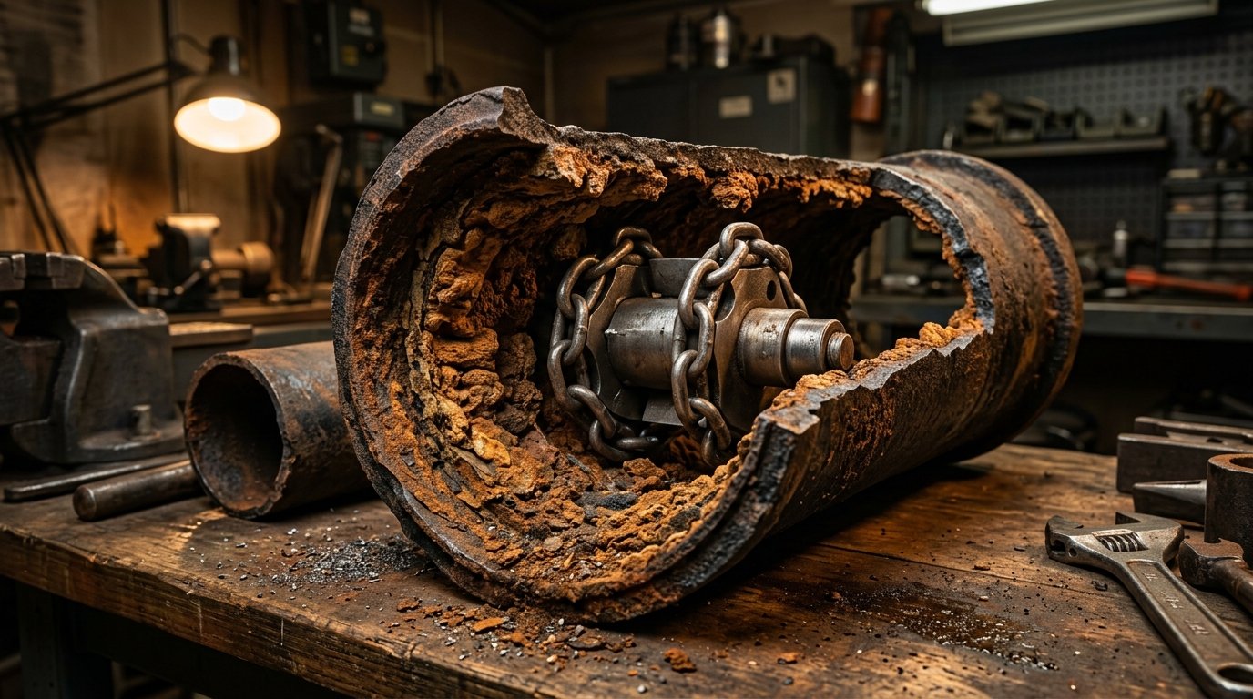
1. The Dual Chemical Engines: Invert Channel Rot vs. Crown Corrosion
Why do commercial cast-iron sewer pipes fail while municipal water mains in the same building stay solid?
Sewer pipes operate under partial flow (gravity drainage). The bottom of the pipe carries liquid wastewater, while the top half of the pipe contains moist sewer air.
This hydraulic environment creates two totally separate, hyper-aggressive chemical attack zones:
| Degradation Mechanism | Pipe Geometry Zone | Primary Chemical / Biological Agent | Physical Structural Impact |
|---|---|---|---|
| Bottom Channel Rot (Invert Erosion) | Bottom 120 Degrees (Flow Channel) | Abrasive grease, sand, acidic soda pop, caustic chemical drain openers, and grease scouring. | Carves a smooth, knife-edge groove through the bottom wall. The bottom vanishes completely, washing out structural soil bedding! |
| Crown Corrosion (MIC Acid Attack) | Top 120 Degrees (Air Headspace) | Hydrogen sulfide gas ($H_2S$) converted into **pure sulfuric acid ($H_2SO_4$)** by aerobic Thiobacillus bacteria. | Dissolves the pipe crown into a soft, yellow-white gypsum paste. The top of the pipe collapses under concrete slab load! |
| Internal Tuberculation | 360 Degrees Internal Perimeter | Ferric hydroxide ($Fe(OH)_3$) and calcium carbonate crust formed by anaerobic electrochemical cells. | Jagged rust mounds narrow pipe internal diameter by up to 60%, acting like Velcro for paper and solid waste. |
🧪 The Biochemistry of Microbial Induced Corrosion (MIC)
In sluggish commercial sewer runs, anaerobic bacteria in bottom sludge reduce organic sulfates into hydrogen sulfide gas ($H_2S$).
The $H_2S$ gas off-gasses into the pipe headspace. There, it condenses against the damp pipe ceiling. Aerobic bacteria (specifically Acidithiobacillus ferrooxidans) living on the moist iron oxidize the $H_2S$ gas into concentrated sulfuric acid:
$$H_2S + 2O_2 \xrightarrow{\text{Bacteria}} H_2SO_4$$
The sulfuric acid attacks the cast-iron wall, converting metallic iron into soft, soluble ferrous sulfate ($FeSO_4$). Over ten to twenty years, a 3/8-inch solid iron pipe ceiling is eaten away down to the thickness of a postage stamp!
2. Invert Channel Rot: The Invisible Sub-Slab Void Hazard
When the bottom of a buried cast-iron pipe dissolves away, property owners rarely see water backing up initially.
Every time tenants flush toilets or commercial kitchens wash dishes, wastewater discharges directly into the soil beneath the building foundation.
This creates an acute geotechnical liability across Broomfield’s expansive bentonite clay:
- Soil Hydro-Compaction & Voids: Escaping sewage washes fine sand and gravel bedding downstream into the municipal sewer, carving massive subterranean underground cavern voids beneath the concrete slab.
- Foundation Heave & Cracking: Highly expansive Front Range clays absorb millions of gallons of sewage water, swelling with pressures exceeding **10,000 pounds per square foot (PSF)**. Slabs crack, tile floors tent upward, and structural steel support columns displace!
- Radon & Sewer Gas Invasion: The collapsed bottom invert provides an open channel for explosive methane and carcinogenic radon gas to migrate into the building foundation.

3. Why Chemical Cleaners Accelerate Cast Iron Destruction
When commercial drains slow down, building janitors often dump caustic lye (sodium hydroxide) or commercial sulfuric acid down the line.
This practice is an absolute catastrophe for aging cast iron:
â˜ ï¸ The Acid Drainage Trap
Heavy commercial chemical drain openers have a specific gravity of nearly 1.84 (almost twice as heavy as water).
The acid sinks straight to the bottom of the pipe and pools in the low spots and bellies.
Instead of clearing the clog, the concentrated acid reacts violently with the degraded cast iron, generating intense exothermic heat ($T > 220^\circ\text{F}$) that shatters brittle cast-iron joints and eats through the remaining metal within seventy-two hours!
4. Mechanical Descaling: High-Speed Picote Chain Milling
In the past, severely scaled cast iron left property owners with only one option: jackhammering through structural concrete slabs, destroying expensive marble tile and commercial flooring.
Today, master commercial plumbers restore cast iron non-invasively using **high-speed flexible-shaft mechanical chain knockers (Picote Maxi Miller / Ridgid K9)**:
| Descaling Tool | Rotational Speed & Drive | Mechanical Action | Pipe Wall Restoration Result |
|---|---|---|---|
| Carbide-Tipped Cyclone Chain Knocker | 1,800 to 2,200 RPM via enclosed flexible steel shaft | Centrifugal force flings circular hardened tungsten carbide chain links flush against 360 degrees of the inner pipe circumference. | Shatters brittle iron tuberculation and petrified calcium scale, scraping the pipe interior down to clean, smooth gray metal. |
| Picote Smart Cutterâ„¢ Hub | 2,000 RPM with diamond/carbide abrasive panels | Grinds jagged metal rust fins and lateral branch intruding pipe stubs flush with the main host pipe wall. | Prepares an ultra-smooth cylindrical substrate perfectly profiled for epoxy structural lining. |
| Water-Assisted Rotary Descaling Flush | Low-pressure flushing water (20 PSI @ 5 GPM) while milling | Sweeps pulverized iron rust dust downstream into an extraction cleanout before it can settle and cement. | Leaves the pipe completely debris-free without exerting hydraulic pressure on weakened pipe crowns. |
5. Trenchless Structural CIPP Epoxy Lining: Rebuilding the Pipe from Within
Once the cast iron is milled clean of tuberculation, what prevents raw sewage from leaking through the missing bottom channel?
Master commercial plumbers deploy **Cured-in-Place Pipe (CIPP) Structural Epoxy Inversion Lining**:
- Full-Length CCTV Video Audit: A digital self-leveling sewer camera maps every inch of the host pipe, measuring exact lengths, offsets, and connection locations of incoming restroom branches.
- Epoxy-Impregnated Felt Liner Preparation: A non-woven polyester needle-felt tube coated with an impermeable polyurethane outer membrane is saturated (wet-out) under vacuum with a high-performance **two-part commercial epoxy resin** engineered for ASTM F1216 structural compliance.
- Compressed Air Inversion: The liner is inserted through an existing cleanout; compressed air shoots the flexible tube inside-out through the degraded cast iron pipe. The wet epoxy presses tightly against the host pipe walls, bridging missing bottom channels and structural fractures.
- Thermal / UV Steam Cure: Controlled steam or ultraviolet light arrays cure the epoxy into a rock-hard, seamless structural composite pipe within three hours.
- Robotic Lateral Reinstatement: A remote-controlled robotic cutting unit (Picote Smart Spider) travels inside the newly lined main, surgically cutting open all covered lateral branch tee connections with sub-millimeter precision.
📠Manning’s Equation: Restoring Flow Dynamics
$$Q = \frac{1.486}{n} \cdot A \cdot R_h^{2/3} \cdot S^{1/2}$$
Old, corroded cast iron has a rough Manning’s roughness coefficient of $n = 0.015\text{ to }0.018$.
The newly installed smooth epoxy liner has a glass-like Manning’s coefficient of $n = 0.009$.
Even though the liner reduces internal diameter by roughly 1/4 inch, total gravity flow capacity actually INCREASES by up to 25%, completely eliminating recurring paper clogs and grease backups for fifty years!
🚨 Emergency Commercial Cast Iron Drain Service in Broomfield
Are commercial basement drains backing up with rust chunks? Has a drain camera revealed bottom channel rot or severe crown acid pitting?
Call our 24/7 commercial emergency master plumbers at (303) 647-3363. We dispatch commercial drain restoration crews equipped with high-speed Picote chain knockers, robotic reinstatement cutters, digital CCTV inspection cameras, and ASTM F1216 certified structural CIPP lining rigs.
Commercial Sump Basin Radon & Soil Gas Barrier Failures: Sub-Slab Depressurization, EPDM Gasket Permeation & Colorado Zone 1 Standards
Step into the subterranean basement mechanical room of a three-story corporate office building off Destination Drive in Broomfield during the middle of January. Outside, snow covers the ground, and ambient temperatures sit at 14°F. Up on the second and third floors, commercial HVAC air handlers are roaring, pulling thousands of cubic feet of warm air upward through elevator shafts and stairwells in a powerful thermal updraft known as the **stack effect**.
Down in the basement, that upward chimney draft creates a continuous negative pressure zone of negative six to ten Pascals (-6 to -10 Pa) relative to the surrounding earth.
Over in the corner of the floor slab sits a heavy diamond-plate commercial sewage ejector and groundwater sump crock.
The perimeter neoprene lid gasket, installed eight years ago, has dried out, hardened, and shrunk by a quarter of an inch.
Through that microscopic gap around the perimeter of the lid, a continuous, invisible draft of subterranean gas is being sucked into the building.
There is no rotten egg smell. There is no visible smoke.
Yet a digital continuous radon monitor mounted four feet above the concrete slab flashes an emergency warning: **24.8 picocuries per liter (pCi/L)**—more than six times the EPA actionable health threshold!
Broomfield and Boulder counties sit squarely inside **EPA Radon Zone 1**, a geological region characterized by uraniferous granitic bedrock, Pierre shale, and high-permeability gravel formations. In commercial facilities, below-grade plumbing sumps are the primary structural breach through which radioactive radon gas ($^{222}Rn$), methane, and volatile organic compounds (VOCs) invade occupied workspaces.
Under **ANSI/AARST RMS-LB (Radon Mitigation Standards for Larger Buildings)**, the International Plumbing Code (IPC Section 712), and Colorado building health regulations, commercial drainage basins must be engineered as hermetically sealed environmental pressure barriers. Let’s dissect the physics of sub-slab soil gas transport, inspect elastomeric gasket permeation, examine Active Soil Depressurization (ASD) interactions, and review master plumber hermetic sealing protocols.
1. The Geological Reality: Why Front Range Basements Are Radioactive Sinks
Why is radon gas such a severe hazard along the Colorado Front Range?
Radon-222 is a naturally occurring radioactive noble gas produced by the radioactive decay chain of Uranium-238 present in Rocky Mountain granite.
Unlike mineral scale or waterborne bacteria, radon is an unreactive, inert gas:
- It carries zero color, zero odor, and zero chemical taste.
- It has a specific gravity of **9.73 (nearly eight times heavier than air)**.
- Because it is an inert noble gas, it does not bind to soil particles. It migrates freely through subterranean fractures, porous gravel bedding, and crushed aggregate beneath commercial concrete floor slabs.
â˜¢ï¸ The Alpha Particle Radiation Hazard
Radon has a radioactive half-life of 3.82 days. As it decays, it transforms into solid radioactive polonium isotopes ($^{218}Po$ and $^{214}Po$).
When office workers or hotel guests inhale indoor air containing elevated radon, these microscopic radioactive daughters attach directly to lung bronchial tissue. When they decay, they emit high-energy alpha particles ($5.49\text{ MeV}$)—microscopic atomic cannonballs that shatter DNA strands in pulmonary epithelial cells.
According to the EPA and the CDC, radon gas exposure is the number-one leading cause of lung cancer among non-smokers in the United States, causing over 21,000 fatalities annually!
2. The Stack Effect & Soil Gas Advection: The Hydraulic Suction Engine
How does gas buried six feet beneath a concrete slab get pulled into a commercial building?
Subterranean soil gas does not merely diffuse slowly through concrete; it is driven by **bulk advective pressure differentials**:
📠The Building Thermal Stack Effect Equation
$$\Delta P_{\text{stack}} = \rho_o \cdot g \cdot h \cdot \left(\frac{T_i – T_o}{T_i}\right)$$
Where:
- $\Delta P_{\text{stack}}$ = Driving pressure differential between basement and outdoor atmosphere (Pascals)
- $\rho_o$ = Outdoor air density ($1.225\text{ kg/m}^3$)
- $g$ = Gravitational acceleration ($9.81\text{ m/s}^2$)
- $h$ = Total vertical height of the commercial building (meters)
- $T_i, T_o$ = Absolute indoor and outdoor temperatures (Kelvin)
In a five-story commercial office building in Broomfield during winter, the stack effect generates a continuous basement vacuum of -8 to -15 Pascals.
A commercial sump basin is a direct, unshielded 36-inch hole punched through the concrete slab into the crushed rock drainage base. That open hole acts as a massive vacuum intake, sucking hundreds of cubic feet of concentrated radioactive soil gas (often measuring 2,000 to 10,000 pCi/L under the slab) directly into the building’s air supply!

3. Anatomy of a Basin Barrier Failure: Why Cheap Covers Leak
Many commercial properties built prior to 2015 feature basic sheet-metal or plywood split-covers loosely bolted over ejector pits.
Four mechanical weak points destroy the gas barrier:
| Failure Point | Mechanical Weakness | Gas Infiltration Mechanism | Master Plumber Solution |
|---|---|---|---|
| Perimeter Lid Gasket | Standard open-cell sponge rubber or dried butyl tape | Thermal drying, ozone degradation, and grease vapors harden the gasket. Suction pulls radioactive gas past warped steel flanges. | Install continuous 3/8-inch closed-cell **EPDM elastomeric compression foam** or 100% silicone O-ring bead torqued to 35 ft-lbs. |
| Pipe Discharge Penetrations | Crude oversized holes cut into the cover around 2-inch or 3-inch discharge pipes | Unsealed annular gaps act like open chimneys venting radon and methane into the mechanical room. | Deploy **cast-iron compression flange hubs** or heavy-duty neoprene mechanical pipe grommets clamped with stainless-steel worm bands. |
| Electrical Cable Pass-Throughs | Pump power cords and float switch wires draped loosely through open cover slots | Gases travel through the hole; even worse, gas migrates inside the hollow electrical conduit straight into electrical panels! | Install **liquid-tight, gas-tight cord grip compression bushings**; pack and pour Chico® EYS explosion-proof conduit sealing fittings. |
| Observation / Inspection Portals | Unsealed inspection hatches or missing portal plugs | Maintenance technicians remove access bolts to view floats and fail to re-seal the port. | Install an engineered **clear 1/2-inch polycarbonate viewing window** fitted with a bolted O-ring flange, allowing visual inspection without unsealing the pit! |
4. Active Soil Depressurization (ASD) Interactions: The Trap Siphon Threat
Commercial facilities often install commercial Active Soil Depressurization (ASD) radon mitigation systems: high-flow centrifugal inline fans (such as RadonAway or Fantech commercial units) pulling negative pressure from beneath the slab through 4-inch or 6-inch PVC vent stacks.
Here is the dangerous hydraulic conflict that inexperienced contractors overlook:
âš ï¸ The Floor Drain P-Trap Siphon Hazard
A commercial radon fan creates a subterranean vacuum of -150 to -300 Pascals (-0.6 to -1.2 inches of water column) directly beneath the slab.
If unsealed foundation perimeter drain tiles (French drains) connect directly into an open sump basin, that intense sub-slab vacuum pulls against the interior of the building!
If floor drains, trap primers, or emergency floor receptors are dry or unprimed, the radon fan can actually reverse air flow through the building’s drainage traps, sucking foul sewer gases out of dry waste lines and exhausting them through the roof, while pulling contaminated air across occupied tenant offices!
To prevent this, commercial plumbing codes mandate that groundwater dewatering sumps and sewage ejector basins must be **physically and pneumatically decoupled**:
- Groundwater sumps must utilize sealed check valves and dedicated independent trap priming.
- If an ASD radon suction pipe ties into a sump basin, the basin cover must be certified **airtight to 1.5 times the fan’s maximum shutoff suction head**.
- All nearby floor drains must be fitted with **ASME A112.18.8 / ASSE 1072 certified one-way barrier trap seal inserts (Green Drain)** to prevent reverse soil gas infiltration.
5. The Master Plumber Hermetic Sealing Retrofit Protocol
When indoor radon levels or sewer gas leaks breach commercial safety thresholds, our master plumbers execute a rigorous, code-compliant sealing retrofit:
- Sub-Slab Pressure Field Extension (PFE) Audit: Drill 3/8-inch test holes through the basement slab at 20-foot intervals; measure pressure differentials using an Energy Conservatory DG-1000 digital micromanometer to confirm the extent of negative pressure beneath the slab.
- Heavy-Duty Cover Fabrication: Install a custom 1/4-inch aircraft-grade 6061-T6 aluminum or 304 stainless-steel gas-tight diamond plate cover engineered to support a 500-pound surface live load.
- Full-Circumference Compression Gasketing: Apply a continuous, unbroken gasket of high-density closed-cell EPDM rubber around the basin rim flange. Fasten with stainless-steel Grade 316 drop-in anchors torqued in a crisscross pattern.
- Hermetic Cord Seal Manifold: Route all pump power leads, sensor wires, and transducer cables through multi-hole neoprene compression grommets mounted in an external junction box.
- Dedicated IPC Section 712 Atmospheric Vent: Ensure the ejector basin vent terminates through the building roof without mechanical restriction, allowing displaced air to escape naturally during pump discharge cycles without pressurizing the lid gasket.
6. Post-Installation Testing: Smoke Testing & Continuous Rad-Link Auditing
How do we prove that a commercial sump basin is 100% gas-tight?
Master commercial plumbers never guess; we verify using **positive-pressure chemical smoke diagnostics**:
- An electric smoke blower injects non-toxic white zinc-chloride diagnostic smoke into the basin under 1.0 inch water column of positive static air pressure.
- Technicians inspect every square inch of the basin perimeter, bolt penetrations, cord grips, and pipe flanges using intense halogen inspection lights.
- If a single wisp of smoke escapes, the fastener is re-torqued and sealed with elastomeric polyurethane sealant until **zero visible smoke leakage occurs**.
- Finally, a continuous digital radon monitor (Radalink or Sun Nuclear 1028-XP) records hourly radon levels for 72 hours, certifying that indoor levels have dropped permanently below **2.0 pCi/L**.
🚨 Emergency Commercial Sump & Radon Plumbing Service in Broomfield
Have indoor radon tests spiked above 4.0 pCi/L? Do your commercial basement sumps smell of sewer gas, or are your ejector lid gaskets cracked and leaking?
Call our 24/7 commercial emergency master plumbers at (303) 647-3363. We dispatch commercial plumbing crews equipped with aircraft-grade aluminum hermetic covers, digital micromanometers, chemical smoke blowers, and certified ANSI/AARST RMS-LB gas-barrier sealing assemblies.
Commercial Water Heater Dip Tube Degradation & High-Velocity Recirculation Line Erosion-Corrosion: ASTM B88 Copper Velocity Limits
At 6:30 AM on a crisp autumn morning inside a 140-room extended-stay hotel off 120th Avenue in Broomfield, the front desk telephone begins ringing continuously. Guests on the third and fourth floors are stepping into morning showers only to be greeted by lukewarm, fifty-degree water. Yet down in the central basement mechanical room, the master thermometer on the 250-gallon commercial gas storage water heater reads a scalding 140°F.
The burners are firing. The primary circulation pumps are humming.
How can a water heater be boiling hot while guest rooms receive tepid water?
Up inside the cold inlet nipple of the commercial storage tank, the polymer **internal dip tube has snapped cleanly in half**.
Instead of directing cold municipal makeup water to the very bottom of the tank to be heated by burner baffles, incoming cold water short-circuits across the top three inches of the tank, pouring straight into the hot water supply riser!
Meanwhile, three floors above in a drywall plumbing chase, a second disaster is brewing:
A rhythmic, high-frequency acoustic hiss whispers from behind the bathroom sheetrock.
A fine, needle-like stream of scalding water is spraying out of a tiny horseshoe-shaped pinhole immediately downstream of a two-inch copper return elbow.
The copper pipe didn’t rot from old age. It was literally scrubbed to paper-thin foil from the inside out by **high-velocity hot water erosion-corrosion**.
Managing commercial domestic hot water (DHW) distribution across multi-story commercial properties requires strict obedience to fluid dynamics, **ASTM B88 copper velocity limitations**, **ASSE 1017 master thermostatic mixing standards**, and thermal stress chemistry. Let’s dissect the engineering physics behind dip tube breakdown, turbulent boundary layer stripping, and recirculation circuit balancing.
1. The Geometry of Stratification: Why Dip Tubes Rule Recovery
Why do commercial water heaters require an internal dip tube in the first place?
Water naturally stratifies by density when heated.
Cold municipal tap water enters at 45°F to 55°F with a density of roughly $62.4\text{ lb/ft}^3$. Hot water at 140°F has an expanded density of $61.38\text{ lb/ft}^3$.
Because lighter hot water rises naturally to the top of the vessel, the hot water outlet pipe draws fluid directly from the tank ceiling.
The cold water inlet, however, also enters through the top tank head.
To prevent incoming cold water from instantly mixing with and cooling down the ready-to-use hot water at the top, an engineered pipe—the **dip tube**—extends from the top inlet spud down to within six inches of the bottom tank floor:
📠The Dip Tube Thermal Stratification Mechanism
By discharging dense incoming cold water directly onto the bottom heating surfaces, the dip tube maintains a sharp thermal boundary layer known as the thermocline.
As hotel guests or commercial dishwashers draw hot water, the hot layer drops smoothly like a floating hydraulic piston, allowing the facility to utilize up to 75% to 80% of the tank’s stored thermal capacity before output temperatures drop by even two degrees!
The Failure Mechanism: Polyolefin Embrittlement & Thermal Hydrolysis
Why do dip tubes break?
In residential tanks, dip tubes are made of extruded polypropylene. In commercial tanks subjected to continuous 140°F to 160°F temperatures, polypropylene suffers from severe **oxidative chain scission**:
- Dissolved chlorine and chloramines in Front Range tap water attack the polymer backbone.
- Combined with continuous thermal stress, the flexible plastic becomes chalky, yellowed, and brittle as dried glass.
- During sudden commercial draw cycles, incoming water creates hydraulic shock pulses that snap the brittle tube off at the brass nipple threads.
- The bottom three feet of the tube drops into the tank sludge blanket.
Once the tube breaks, cold water dumps directly into the hot outlet. Within two minutes of water draw, tenant faucets run cold even though hundreds of gallons of boiling water sit trapped below!
Master commercial plumbers solve this by replacing plastic tubes with **Schedule 40 seamless 304 stainless-steel or heavy-wall Type K copper commercial dip tubes** equipped with anti-siphon vacuum relief ports.

2. The ASTM B88 Copper Velocity Rule: The Hot Water Limit
Why do hot water return lines develop pinhole sprays while cold water lines in the same building last fifty years?
The answer lies in fluid velocity, temperature, and copper metallurgy governed by **ASTM B88** and the Copper Development Association (CDA):
âš–ï¸ CDA & IPC Fluid Velocity Ceilings for Copper Pipe
- Cold Water Lines (< 120°F): Maximum allowable velocity = 8.0 feet per second (fps).
- Hot Domestic Water Lines (120°F to 140°F): Maximum allowable velocity = 5.0 feet per second (fps).
- High-Temperature Commercial Loops (> 140°F): Maximum allowable velocity = 4.0 to 4.5 feet per second (fps).
Look closely at that drop from 8.0 fps down to 4.0 fps.
Why does hot water cut the allowable velocity in half?
Copper piping protects itself against corrosion by forming an ultra-thin, microscopic chemical barrier film of **cuprous oxide ($Cu_2O$)** and **cupric oxide ($CuO$)** on its inner pipe walls:
$$4Cu + O_2 \to 2Cu_2O$$
This dark brown oxide layer is self-passivating. It seals the raw copper metal away from oxygen and mineral attack.
However, as water temperature rises above 130°F, water viscosity decreases, while molecular kinetic energy skyrockets.
When water velocity exceeds 5.0 fps, fluid flow transitions from smooth laminar stream into violent, swirling **turbulent eddy currents** ($Re > 4,000$).
3. Anatomy of Horseshoe Cavitation Pitting
Turbulent water striking an internal directional change—such as the inner throat of a 90-degree copper elbow or an unreamed pipe burr—creates microscopic low-pressure separation zones:
| Stage | Fluid Dynamic Phenomenon | Metallurgical Impact on Copper Wall | Visual Plumber Symptom |
|---|---|---|---|
| 1. Boundary Layer Shear | Fluid velocity > 5 fps creates intense shear stress along pipe inner wall. | Mechanical shear strips the soft, protective cupric oxide passivating film down to bare, shiny metal. | Bright salmon-pink bare copper exposed inside the fitting throat. |
| 2. Galvanic Couple Formation | Tiny bare copper spot is surrounded by a large area of intact copper oxide film. | A micro-galvanic electrochemical cell forms! The bare copper acts as a tiny active anode; the large oxidized pipe acts as a giant cathode. | Pinhole corrosion rate accelerates by 500% at the localized bare spot. |
| 3. Horseshoe Pit Gouging | Water flow wraps around the microscopic pit, forming dual counter-rotating vortices. | Hydraulic vortices carve a distinct **horseshoe-shaped indentation** pointing downstream into the metal. | Sharp U-shaped gouge visible under cross-sectional metallurgical inspection. |
| 4. Full Wall Blowout | Wall thickness thins from 0.045 inches (Type L) down to paper-thin foil. | Internal line pressure (65 to 80 PSI) punches through the exhausted metal, releasing a high-velocity pinhole spray. | Ceiling drywall saturates; water tracks along floor slabs fifty feet from the leak. |
🚫 The Unreamed Pipe Burr Catastrophe
When an apprentice plumber cuts copper pipe with a roller cutter, the wheel rolls a sharp inward metal lip (burr) into the pipe bore, reducing internal diameter by up to 20%.
If the technician fails to ream that burr clean with a reamer blade, high-speed hot water striking that inward metal blade creates a standing hydraulic supersonic jet directed straight at the pipe wall immediately downstream. That unreamed burr will carve a pinhole leak through a commercial copper line in less than twenty-four months!
4. Sizing Recirculation Pumps: The Temperature-Drop Heat Loss Method
Why do commercial buildings end up with excessive pipe velocity?
Inexperienced plumbing contractors frequently install oversized, high-horsepower circulator pumps (such as a 1/2-HP inline pump where a 1/12-HP pump was required) under the false belief that “more flow equals faster hot water.”
Master commercial plumbers calculate recirculation flow rates using the **ASHRAE Heat Loss Equation**:
📠Recirculation Pump Flow Rate Equation
$$Q = \frac{q}{500 \cdot \Delta T}$$
Where:
- $Q$ = Recirculation flow rate required (GPM)
- $q$ = Total structural heat loss of the insulated distribution piping (BTU/hr)
- $\Delta T$ = Maximum allowable temperature drop between supply and return (typically 5°F to 10°F)
- $500$ = Fluid heat capacity constant ($8.33\text{ lb/gal} \times 60\text{ min/hr} \times 1.0\text{ BTU/lb}\cdot^\circ\text{F}$)
For a typical multi-story commercial complex with 15,000 BTU/hr of total insulated riser heat loss and a target 5°F drop:
$$Q = \frac{15,000}{500 \times 5} = \mathbf{6.0\text{ GPM}}$$
A tiny flow of just 6.0 GPM is all that is required to keep the entire building loop instant-hot! Pumping 25 GPM through that same 1-inch pipe spikes velocity to 9.5 fps, guaranteeing catastrophic erosion-corrosion failure!
5. Dynamic Thermal Balancing: Circuit Setters vs. Thermostatic Valves
In a multi-story building with ten vertical supply risers, water naturally takes the path of least resistance: it short-circuits through the riser closest to the water heater, starving the distant risers.
To ensure balanced, non-erosive velocity across all risers, master plumbers install **engineered balancing valves**:
| Balancing Technology | Operating Mechanism | Maintenance Requirements | Master Plumber Evaluation |
|---|---|---|---|
| Manual Calibrated Orifice (Bell & Gossett Circuit Setter) | Multi-turn dial with dual readout pressure ports; flow rate is tuned manually using a differential manometer. | Requires field balancing during initial commissioning; fixed position cannot adapt to changing tenant flow patterns. | Reliable, heavy-duty bronze; excellent for main branch headers. |
| Thermostatic Balancing Valve (Caleffi ThermoSetter / Armstrong) | Modulating internal thermal wax element; automatically throttles flow down to a trickle (0.5 GPM) once return water reaches 130°F. | Zero manual balancing required; continuously self-adjusts across all building risers in real time. | THE COMMERCIAL GOLD STANDARD. Drastically cuts pump electrical draw and prevents velocity erosion. |
| Electronic Smart Actuator Valves (Taco eSmart) | Digital temperature sensor interlocked with a modulating motor actuator wired to the building automation system. | Software monitoring; high initial capital cost. | Ideal for high-spec hospitals and pharmaceutical labs requiring digital continuous temperature validation. |
6. Emergency Diagnostics & Repair Workflow
When tenant hot water complaints surge or pinhole leaks appear behind drywall, execute this master plumber diagnostic sequence:
- Touch-Test Water Heater Inlets: Feel the cold water inlet pipe three feet above the tank during an active hot water draw. If the cold pipe is hot to the touch, or if outlet temperature plummets while the burner continues firing, extract the cold inlet nipple and inspect for broken plastic dip tube shards.
- Ultrasonic Pipe Flow Audit: Clamp a transit-time digital ultrasonic flow meter onto the main hot water return header. If flow exceeds 5.0 fps, immediately throttle the circulator discharge isolation valve or downsize the pump impeller.
- Infrared Thermal Mapping of Chases: Scan vertical riser drywall with a FLIR thermal camera to detect concealed pinhole sprays and localized heat saturations before water rots structural framing.
- Eliminate Unreamed Fittings: When cutting out eroded copper fittings, inspect the failed elbow. If a sharp ridge is present on the pipe end, deburr and ream all replacement copper ends using high-speed fluted deburring tools.
🚨 Emergency Commercial Domestic Hot Water Service in Broomfield
Are guests complaining of cold showers? Have mysterious pinhole leaks erupted in your commercial building copper piping?
Call our 24/7 commercial emergency master plumbers at (303) 647-3363. We dispatch commercial service trucks equipped with stainless-steel dip tubes, ultrasonic Doppler flow meters, thermostatic balancing valves, and certified copper press repair equipment to restore your hot water safely.