
Table of Contents: Sump Pump Engineering & Basement Flood Mitigation Guide
- 1. Executive Summary: The Hydrogeology of Colorado Basement Inundation
- 2. Anatomy of Catastrophic Sump Failure: Float Switches, Impellers & Check Valves
- 3. Fluid Mechanics & Hydraulic Sizing: Total Dynamic Head (TDH), Hazen-Williams & Pump Affinity Laws
- 4. Electrical Engineering & Inverter Dynamics: LRA, Pure Sine Wave & Battery Storage Physics
- 5. Engineering Fail-Safe Redundancy: Primary AC Pumps & Deep-Cycle Battery Backups
- 6. Comprehensive System Comparison: Standard AC vs. Dual Hybrid vs. Water-Powered vs. Generator
- 7. Master Plumber Installation & Commissioning Protocol: Basin, Check Valve & Daylight Run
- 8. Preventative Maintenance & Semi-Annual Engineering Diagnostic Audit Protocol
- 9. Colorado Front Range Submarket Hydrogeology: Snowmelt, High Water Tables & Soil Heave
- 10. Financial Risk Assessment: Mitigation Costs vs. Catastrophic Water Damage Restoration
- 11. Comprehensive Extended FAQ Section (12 Detailed Engineering Questions)
- 12. 24/7 Emergency Sump Pump Replacement & Flood Prevention Services
1. Executive Summary: The Hydrogeology of Colorado Basement Inundation
For homeowners living along the Colorado Front Range, a finished basement represents essential living space, housing family entertainment rooms, guest bedrooms, home offices, and costly mechanical equipment. Yet, this subterranean perimeter exists under relentless hydrogeological pressure. Situated directly down-gradient from the Rocky Mountain foothills, communities across Broomfield, Westminster, Thornton, and Arvada experience intense hydrostatic groundwater pressure driven by rapid spring snowmelt, torrential late-spring cloudbursts, and saturated alluvial soil formations.
The single mechanical barrier standing between an arid, livable subterranean environment and catastrophic structural flooding is the residential submersible sump pump system. Operating quietly inside a perforated excavation pit beneath the basement slab, this electromechanical workhorse is designed to intercept subterranean water table migration through perimeter French drain weeping tiles and pump it safely out and away from the foundation foundation footing.
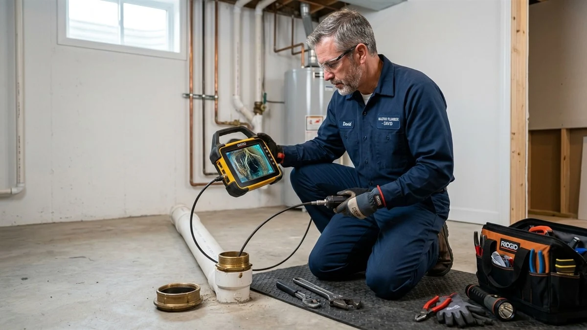
Tragically, standard builder-grade sump pumps are single points of failure prone to mechanical breakdowns precisely when hydrological stress reaches its absolute maximum. When severe severe thunderstorms knock out local electrical grids, primary AC pumps instantly stall. If a mechanical tethered float switch catches on a basin wall, or an impeller jams on silt, incoming groundwater rises unchecked. Within forty-five minutes, hydrostatic pressure pushes water up through foundation expansion joints, soaking drywall, ruining carpet, breeding toxic black mold (Stachybotrys chartarum), and destroying high-value HVAC equipment.
Achieving true peace of mind requires a rigorous engineering approach: implementing dual-pump redundancy, sizing equipment according to precise Total Dynamic Head (TDH) fluid mechanics, incorporating high-capacity AGM or Lithium-Iron-Phosphate (LiFePO4) battery backup systems, and deploying smart IoT telemetry monitors. This comprehensive technical guide provides an exhaustive engineering examination of sump pump failure modes, fluid mechanics sizing protocols, redundant battery backup topologies, and regional flood mitigation realities across the northern Denver metropolitan area.
2. Anatomy of Catastrophic Sump Failure: Float Switches, Impellers & Check Valves
A submersible sump pump is a specialized centrifugal pumping apparatus operating in a hostile, chemically aggressive, and sediment-laden environment. Understanding why these machines fail requires analyzing their electro-mechanical sub-assemblies:

1. Float Switch Mechanical Jamming and Carbon Arc Degradation
Statistical field audits reveal that over 65% of all premature sump pump failures originate in the liquid level sensing switch rather than the motor itself. Builder-grade systems frequently utilize cheap tethered mechanical float switches—hollow plastic bulbs containing a steel ball bearing rolling across electrical contacts. As the pump vibrates during high-torque startup, the flexible cord shifts, causing the float bulb to become pinned against the discharge pipe or the corrugated crock wall. If the float hangs downward, the pump never turns on, causing an overflow. If it wedges in the upward position, the pump runs dry indefinitely, scorching motor bearings and melting the mechanical shaft seal.
Higher-tier systems utilize vertical magnetic reed switches or solid-state conductive capacitive probes that eliminate mechanical pivot friction and prevent carbon contact arcing, drastically boosting duty-cycle reliability from 50,000 cycles to over 500,000 cycles.
2. Impeller Cavitation, Silt Abrasion & Foreign Object Jamming
Centrifugal impellers rotate at 3,450 RPM inside a volute casting. Front Range groundwater contains high concentrations of pulverized granite sand, bentonite clay particles, and calcium minerals washed down from foothill drainages. Standard thermoplastic impellers suffer rapid abrasive wear, rounding off impeller vanes and degrading hydraulic discharge capacity. Furthermore, small gravel chips entering through unlined sump basin perforations can mechanically lock the impeller. When an impeller locks, the electric motor draws locked-rotor amperage, tripping the thermal overload protector within three to five seconds and disabling the pump.
3. Discharge Check Valve Failure & Destructive Water Hammer
Every sump discharge pipe must incorporate a spring-loaded or flapper-style one-way check valve. When the pump shuts down, the check valve snaps closed to prevent the elevated vertical water column in the discharge pipe from draining back into the basin. If the check valve flapper cracks, warps, or gets propped open by mineral scale, gallons of ejected water drain back into the pit the moment the pump stops. This triggers rapid “short-cycling”: the pump runs every thirty seconds, overheating the motor windings and depleting operational lifespans by 80%.
4. Hydraulic Air Locking in the Volute Casing
When an empty sump crock fills rapidly with turbulent, aerated groundwater, trapped air pockets can become compressed inside the pump volute casing directly beneath the spinning impeller. Centrifugal pumps cannot pump air; the impeller spins in an air void without generating hydraulic lift, leaving the motor running continuously while water rises to the basement ceiling. Plumbers must drill a calibrated 3/16-inch weep hole in the PVC discharge pipe between the pump discharge nozzle and the check valve to provide an exhaust vent for trapped air.
3. Fluid Mechanics & Hydraulic Sizing: Total Dynamic Head (TDH), Hazen-Williams & Pump Affinity Laws
Selecting a sump pump based solely on nominal horsepower (e.g., “1/3 HP” or “1/2 HP”) is a dangerous amateur practice. Proper sump pump specification requires rigorous calculation of Total Dynamic Head (TDH), peak volumetric inflow rate, and centrifugal pump performance curves.

The Total Dynamic Head (TDH) Formula
Total Dynamic Head represents the total equivalent height in feet of fluid that the pump must overcome to eject water out of the foundation to daylight:
Where:
- H_static (Static Lift): The actual vertical elevation difference measured from the bottom of the sump pit to the highest elevation point of the exterior discharge pipe run (typically 9 to 11 feet in residential walk-out or deep basements).
- H_friction (Friction Head Loss): The internal drag resistance generated as fluid flows through smooth Schedule 40 PVC pipe, 90-degree elbows, 45-degree bends, and check valves. This is calculated using the Hazen-Williams formula:
Where $L$ is total equivalent pipe length (including equivalent length allowances of 8.5 feet per standard 90-degree elbow), $Q$ is flow in GPM, $C$ is the Hazen-Williams roughness coefficient (150 for PVC), and $D$ is internal pipe diameter.
The Centrifugal Pump Affinity Laws
The mathematical relationships governing centrifugal pump performance are defined by the Affinity Laws:
These equations state that volumetric discharge ($Q$) varies directly with rotational shaft speed ($N$), generated dynamic head ($H$) varies with the square of shaft speed, and consumed motor power ($P$) varies with the cube of shaft speed. If motor supply voltage drops by merely 10% during a severe grid brownout, rotational speed drops, cutting pump head capacity by over 19% and reducing flow by 27%, which can precipitate immediate basin overflow!
Hydraulic Impact of Pipe Sizing: 1.5-inch vs. 2.0-inch PVC
Consider a standard residential basement scenario: static lift of 10 feet with a 40-foot total pipe run and three 90-degree sweep elbows discharging 50 GPM:
- With 1.5-inch Schedule 40 PVC ($D = 1.610″$): Fluid velocity reaches a turbulent 7.9 feet per second, creating approximately 8.2 feet of friction head loss. Total Dynamic Head = 10 ft + 8.2 ft = 18.2 Feet of TDH. At this high head, a standard 1/3 HP pump drops from 50 GPM down to an inadequate 18 GPM, causing an inevitable basin overflow during a severe storm!
- With 2.0-inch Schedule 40 PVC ($D = 2.067″$): Fluid velocity drops to a smooth 4.79 feet per second, reducing friction head loss to merely 2.1 feet. Total Dynamic Head = 10 ft + 2.1 ft = 12.1 Feet of TDH. Sizing the discharge to 2-inch PVC allows a 1/2 HP pump to deliver a robust 48 GPM, effortlessly evacuating peak storm runoff!
4. Electrical Engineering & Inverter Dynamics: LRA, Pure Sine Wave & Battery Storage Physics
When utility power fails during a summer cloudburst, transferring a high-torque inductive electric motor to battery power requires specialized electrical engineering considerations:
Locked Rotor Amperage (LRA) and Startup Surge
A standard 1/2 HP permanent split capacitor (PSC) sump motor draws approximately 6 to 9 full-load running amps (FLA) at 120V AC. However, at the instant of startup, when the stationary rotor must accelerate from 0 to 3,450 RPM against a heavy column of water, the motor draws Locked Rotor Amperage (LRA) of 25 to 35 Amps for 200 to 400 milliseconds. Cheap modified sine wave power inverters collapse under this instantaneous inductive surge, causing inverter fault lockouts. Heavy-duty auxiliary sump battery backup controllers must incorporate Pure Sine Wave Inverters with toroidal transformer cores capable of sustaining surge loads of 250% to 300% of nominal rating.
Electrochemical Battery Discharge Runtime Calculation
Estimating real-world operational runtime requires calculating available watt-hours adjusted for the Peukert Effect (which reduces usable capacity at high discharge rates) and Depth of Discharge (DoD) limits:
Where:
- V_batt: Nominal battery bank voltage (12.8V DC)
- Ah_batt: Rated battery capacity (100 Amp-Hours)
- DoD: Depth of Discharge factor (0.50 for wet flooded lead-acid, 0.75 for AGM, 0.95 for LiFePO4)
- \eta_inv: Power conversion inverter efficiency (typically 0.88 to 0.92)
- P_pump: Operating wattage of the DC auxiliary pump (typically 120W to 180W)
- Duty_Cycle: Proportion of time the pump operates (e.g., 0.10 for 15 seconds every 2.5 minutes)
Under this rigorous calculation, a 100Ah AGM battery delivers approximately 28 hours of runtime in active storm conditions. A high-performance 100Ah LiFePO4 battery bank delivers 46 hours of continuous flood defense, providing complete security during multi-day grid outages.
5. Engineering Fail-Safe Redundancy: Primary AC Pumps & Deep-Cycle Battery Backups
No mission-critical civil or medical facility relies on a single mechanical pump without automated backup systems. Your home’s foundation deserves the exact same engineering rigor. A resilient basement flood protection strategy incorporates a Dual-Pump Redundancy Architecture:
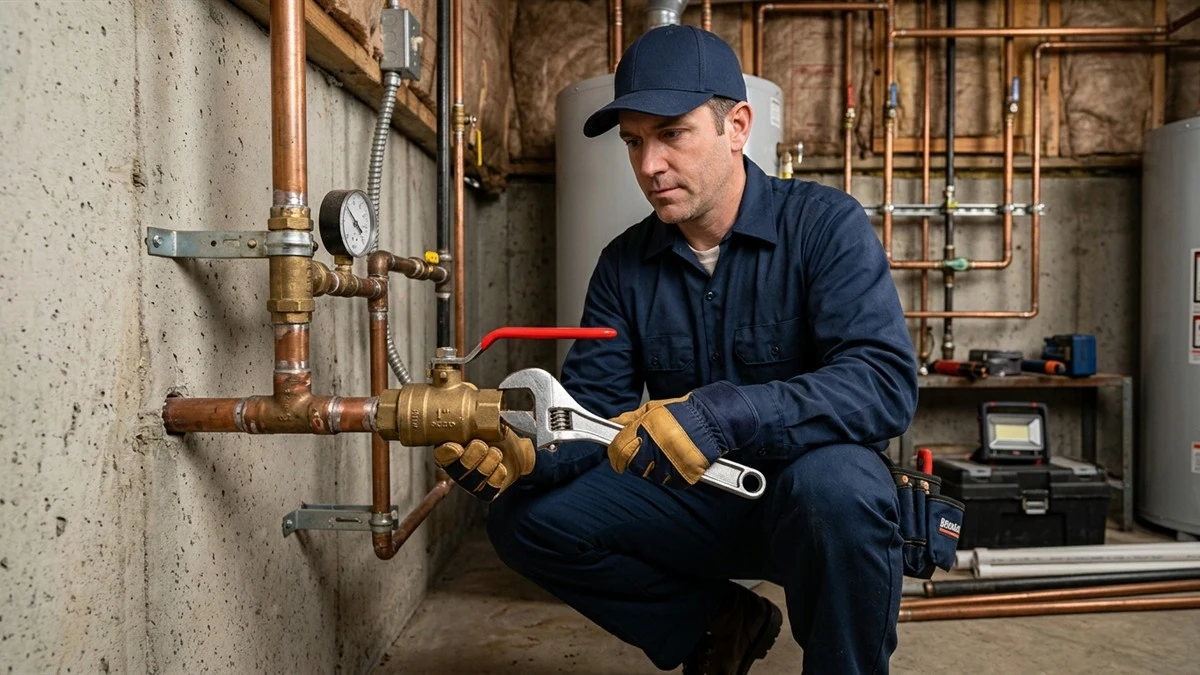
Tier 1: Heavy-Duty Primary Submersible AC Sump Pump
The primary pump should feature a cast iron volute housing, a continuous-duty oil-filled PSC thermal protected motor, dual mechanical carbon/ceramic shaft seals, and a vortex or non-clogging cast bronze impeller. Sized at 1/2 HP or 3/4 HP, this unit handles day-to-day groundwater table control, discharging between 3,000 and 4,500 Gallons Per Hour (GPH) at 10 feet of TDH.
Tier 2: Auxiliary DC Battery-Powered Backup Sump Pump
Positioned directly above the primary pump inside the basin sits an auxiliary 12V or 24V DC high-output backup pump. This pump features its own independent solid-state float switch calibrated 2 to 3 inches higher than the primary switch. If the primary pump experiences an electrical power blackout, tripped GFCI breaker, jammed float, or motor failure, rising water trips the secondary float, instantly energizing the backup pump.
Smart Cloud Telemetry & Automated WiFi Alerts
Modern dual systems are integrated into residential Wi-Fi networks. Smart controllers monitor battery voltage, charging status, pump cycle counts, and ambient crock water level. If a primary pump fails or water reaches the critical high-level alarm threshold, the system pushes instantaneous SMS notifications to the homeowner’s smartphone and local emergency plumbing dispatchers.
6. Comprehensive System Comparison: Standard AC vs. Dual Hybrid vs. Water-Powered vs. Generator
To assist homeowners in making informed infrastructure investments, the comparison table below contrasts the four primary basement water management topologies:
| System Architecture | Power Loss Protection | Pumping Capacity (at 10′ TDH) | Mechanical Failure Protection | Overall Reliability Rating |
|---|---|---|---|---|
| Standard Builder-Grade Single AC Pump | Zero (Fails immediately) | 1,800 – 2,400 GPH | Zero (Single point of failure) | POOR (High risk) |
| Dual AC/DC Hybrid Battery Backup System | 24 to 72 Hours on Battery | Primary: 3,500 GPH Backup: 2,400 GPH |
Complete (Secondary pump activates automatically) | OUTSTANDING (Gold standard) |
| Water-Powered Auxiliary Sump Pump | Unlimited (Uses municipal water pressure) | 800 – 1,200 GPH (Requires 60+ PSI municipal line) | Independent hydraulic float activation | MODERATE (High city water bill during storm) |
| Dual AC Primary Pumps with Automatic Transfer Generator | Unlimited (Natural gas generator supply) | Primary: 4,000 GPH Secondary: 4,000 GPH |
100% Full-Duty Redundancy | MAXIMUM (Commercial tier) |
7. Master Plumber Installation & Commissioning Protocol: Basin, Check Valve & Daylight Run
A high-performance sump system is only as reliable as the quality of its mechanical installation. Professional master plumbers adhere to rigid commissioning standards to eliminate every potential failure point:
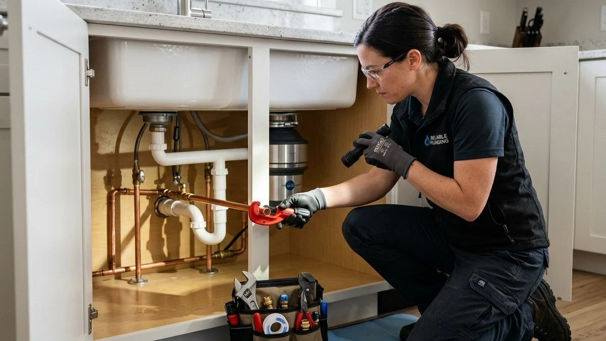
- Basin Crock Sizing & Perforated Aggregate Bedding:
Excavate a sub-slab pit measuring at least 24 inches wide by 30 inches deep. Install a structural polyethylene crock with a gas-tight, radon-sealed gasketed lid. The exterior perimeter of the basin is bedded in 10 inches of washed 3/4-inch crushed granite stone and wrapped in non-woven geotextile filter fabric to block silts and fine sands while maximizing subterranean groundwater collection.
- Vibration-Isolated Foundation Pedestal:
Never place the pump directly onto the raw dirt floor of the crock where settled gravel can be ingested into the impeller. Position the pump assembly on a solid 3-inch elevated polypropylene pump stand or fired clay brick.
- Dual Independent Discharge Lines:
Amateur installations frequently tee the primary and backup pumps into a single 1.5-inch discharge pipe. If that shared line freezes or clogs, both pumps fail simultaneously! Code-compliant engineering requires dedicated, independent 1.5-inch or 2.0-inch discharge pipes for each pump, complete with independent check valves and shutoff valves.
- Anti-Air-Lock Relief Ports:
Drill a 3/16-inch weep hole angled at 45 degrees downward into the discharge pipe 3 inches above the pump collar inside the basin. This prevents volute air entrapment while directing any purge spray safely back into the pit.
- Spring-Loaded Quiet Check Valves:
Replace clattering swing check valves with high-performance spring-loaded “quiet check valves.” These valves feature a pre-loaded spring that closes the flapper gently milliseconds before water momentum reverses, completely eliminating violent hydraulic shock and foundation-shaking water hammer.
- Freeze-Proof Exterior Daylight Discharge:
Colorado winter temperatures plummet below zero degrees Fahrenheit. If an exterior discharge pipe freezes solid with ice, the sump pump burns out against a blocked head within hours. Install an open-air freeze-relief discharge hood (IceGuard) outside the foundation wall. If the buried underground pipe freezes, ejected water spills harmlessly onto the splash block via the open air louvers, preventing basement flooding.
8. Preventative Maintenance & Semi-Annual Engineering Diagnostic Audit Protocol
To guarantee that your basement flood defense system operates flawlessly when extreme weather strikes, homeowners and property managers should execute the following 7-step engineering maintenance protocol every spring (before snowmelt) and autumn (before hard freeze):
- 1. Basin Silt & Aggregate Decontamination: Disconnect electrical power. Remove the airtight crock lid. Inspect the bottom of the sump pit for accumulated granitic sand, decomposed leaves, and bentonite clay silt. Using a wet/dry shop vacuum, extract all settled debris to prevent abrasive particulate from eroding pump seals and impellers.
- 2. Mechanical Float Free-Travel Clearance Verification: Manually lift the primary vertical float switch rod and verify that it glides effortlessly along its stainless steel guide without friction or sticking. Confirm that electrical cords, discharge pipes, and crock walls maintain at least 2 inches of physical clearance from the float bulb.
- 3. Dynamic Water Injection & Duty Cycle Testing: Introduce 5 to 10 gallons of water into the crock using a garden hose or bucket. Observe the pump activation threshold. The motor should engage smoothly without humming, evacuate the basin within 8 to 12 seconds, and de-energize cleanly when the water level drops to within 2 inches of the pump base.
- 4. Check Valve Backflow Seal Inspection: Immediately following pump shutdown, visually inspect the water column inside the clear portion of the check valve or observe the basin water level. The water level must remain completely static. Any upward bubble movement or immediate basin refill indicates check valve flapper leakage requiring replacement.
- 5. Battery Terminal & State of Charge Diagnostic: For DC backup systems, inspect battery terminals for lead-sulfate corrosion. Clean terminals with a wire brush and apply dielectric grease. Using a digital multimeter, verify that the float voltage reads between 13.2V and 13.8V DC under trickle charge. For AGM batteries older than 3 years, perform a calibrated carbon-pile load test.
- 6. Auxiliary Secondary Pump Simulation: Unplug the primary AC pump from the wall receptacle. Pour water into the crock until the water level reaches the elevated auxiliary float switch (typically 3 inches above the primary switch level). Confirm that the backup DC pump activates instantly, sounds crisp, and that the audible and smart WiFi high-water alarm triggers.
- 7. Exterior Daylight Discharge Run Survey: Walk the exterior perimeter of the property to the discharge daylight termination point. Clear away accumulated mulch, fallen autumn leaves, animal nesting materials, and rodent screens. Confirm that the discharge pipe terminates at least 10 to 15 feet away from the foundation wall with continuous positive slope.
9. Colorado Front Range Submarket Hydrogeology: Snowmelt, High Water Tables & Soil Heave
Groundwater risks vary dramatically across individual communities along the Front Range:
- Broomfield (Anthem, Broadlands, Country Vista, McKay Landing): Many Broomfield developments are positioned adjacent to regional reservoirs and open-space drainage corridors. Subsoils consist of Pierre Shale and expansive bentonite clays. When spring moisture saturates the ground, perched water tables rise within 3 to 5 feet of the surface. Sump pumps in the Broadlands routinely run every 90 seconds during April and May, making dual-pump battery redundancy an absolute necessity for protecting finished basements.
- Westminster (Standley Lake, Countryside, Shaw Heights): Homes situated down-gradient from Standley Lake and the Farmers’ High Line Canal encounter continuous hydrostatic pressure from elevated canal seepage and regional irrigation flows throughout the summer. Sump systems in Westminster require 3/4 HP primary motors to overcome high static lifts in homes with deep 9-foot basement ceilings.
- Thornton & Northglenn (Grange Creek, Woodglen, Yorkborough): Built upon historic agricultural alluvial soil plains, Thornton basements frequently suffer from high dissolved iron and calcium mineral deposits in groundwater. These minerals generate “iron ochre”—a sticky, rust-colored bacterial sludge that clogs sump pump impellers and weeping tiles. Systems in Thornton require semi-annual chemical flushing and non-clogging vortex impellers.
- Arvada & West Denver (Leyden Rock, Candelas, Whisper Creek): Situated directly beneath the Rocky Mountain foothills, these newer master-planned communities experience intense subterranean runoff during spring snowmelt. Deep foundation drains intercept massive volumes of clear groundwater that must be evacuated rapidly through 2-inch high-flow discharge manifolds.
- Superior, Louisville & Lafayette (Coal Creek Corridor): Communities bordering Coal Creek and Rock Creek have alluvial gravel sub-strata that allow groundwater to surge rapidly during intense spring rains. Basements in these areas require sealed radon lids and dual-battery configurations capable of surviving prolonged regional grid failures caused by high foothill windstorms.
10. Financial Risk Assessment: Mitigation Costs vs. Catastrophic Water Damage Restoration
Investing in a high-performance redundant sump pump system represents a fraction of the cost of recovering from a single basement flood event:
| Infrastructure / Damage Category | Estimated Out-of-Pocket Cost | Insurance Coverage Reality | Financial ROI |
|---|---|---|---|
| Professional Dual AC/DC Sump Installation | $2,400 – $4,200 (Turnkey system with LiFePO4 battery) | One-time capital improvement; may qualify for home insurance discounts. | 10x to 20x ROI on avoided flood claims. |
| Finished Basement Flooding (2 to 4 Inches of Water) | $25,000 – $65,000+ (Drywall cut, carpet tear-out, antimicrobial drying, furnace replacement) | Standard homeowner’s policies DENY coverage unless optional “Water Backup” rider is present. | Catastrophic financial loss and property depreciation. |
| Typical Water Backup Insurance Rider Cap | $5,000 – $10,000 Max Payout | Leaves homeowner personally responsible for $15,000 to $50,000 in excess damages! | Major out-of-pocket exposure without mechanical redundancy. |
11. Comprehensive Extended FAQ Section
Q1: How long does a quality residential sump pump typically last?
A builder-grade thermoplastic sump pump lasts between 3 and 5 years under moderate usage. Heavy-duty cast iron pumps engineered with dual mechanical seals, oil-filled motor cavities, and vertical magnetic switches last between 7 and 10 years. In high-water-table areas across Broomfield where the pump cycles dozens of times daily during spring, preemptive replacement is recommended every 5 to 7 years to prevent sudden catastrophic motor burnout.
Q2: Why does my sump pump run continuously even when it isn’t raining?
A pump that runs non-stop usually indicates: (1) A failed check valve allowing water in the vertical pipe to drain back into the pit; (2) A stuck float switch wedged against the crock wall; (3) A rising subterranean water table driven by foothill snowmelt or underground irrigation leaks; or (4) Undersized pump horsepower failing to keep pace with inflow.
Q3: How long will a battery backup sump pump run during a power outage?
Runtime depends on battery chemistry, amp-hour (Ah) rating, and pump cycle frequency. A standard 100Ah AGM deep-cycle marine battery will power an auxiliary DC pump for approximately 24 to 36 hours under a normal 10% duty cycle (pumping 15 seconds every 2.5 minutes). High-capacity dual lithium (LiFePO4) systems can operate up to 72 continuous hours, providing ample safety during prolonged multi-day grid blackouts.
Q4: What size sump pump do I need: 1/3 HP, 1/2 HP, or 3/4 HP?
For most Colorado Front Range single-family homes with standard 8-foot basement ceilings and a moderate water table, a 1/2 HP pump delivering at least 3,500 GPH at 10 feet of Total Dynamic Head is the recommended engineering minimum. For walkout basements with deep 9-to-10-foot ceilings, long horizontal discharge lines over 50 feet, or properties located near reservoirs, a 3/4 HP commercial-grade pump is mandatory.
Q5: Can I plug my sump pump into an extension cord or standard power strip?
No! Sump pumps must be plugged directly into a dedicated 15-amp or 20-amp electrical circuit with a GFCI (Ground Fault Circuit Interrupter) receptacle. Extension cords create severe voltage drops that overheat the motor windings, increase fire risks, and void the manufacturer’s warranty.
Q6: Why is my sump pump making a loud “thump” or “bang” noise when it stops?
That violent thudding sound is hydraulic water hammer. When the pump shuts off, the elevated vertical water column in the discharge pipe slams downward against the closing check valve flapper. Installing a spring-loaded “quiet check valve” with an internal dampening spring eliminates this shock wave, protecting your PVC pipe joints from cracking.
Q7: How do I test my sump pump to make sure it works before a storm?
Pour 5 to 10 gallons of clean water directly into the sump pit using a bucket or garden hose. Observe the pump’s operation: the float switch should rise smoothly, activate the motor, rapidly evacuate the water down to 2 inches from the pit floor, shut off cleanly without stuttering, and the check valve should seal quietly without backflow.
Q8: What is the purpose of the weep hole in the sump discharge pipe?
The weep hole (typically 3/16-inch in diameter) is drilled into the discharge pipe inside the crock between the pump nozzle and the check valve. It provides an escape route for trapped air pockets inside the pump volute casing. Without this relief port, the pump can become “air-locked,” spinning continuously without discharging a single drop of water.
Q9: Are water-powered backup sump pumps a good idea in Colorado?
Water-powered backup pumps use municipal pressurized city water (via the Venturi effect) to evacuate groundwater without electricity or batteries. However, they require at least 60 PSI municipal water pressure and a dedicated 3/4-inch supply line. In areas with high municipal water rates or homes served by private wells, DC battery-powered backup systems provide significantly higher pumping capacity and greater efficiency.
Q10: What should I do if my exterior sump discharge pipe freezes in winter?
If the exterior daylight pipe freezes, disconnect the exterior fitting immediately or install a freeze-relief hood (IceGuard) to allow water to discharge at the foundation wall rather than backing up inside. Pour hot water over the frozen exterior pipe to thaw ice blockages, and ensure the outdoor discharge line maintains a continuous downward slope of at least 1/4-inch per foot to daylight.
Q11: Can a sump pump handle radon gas mitigation?
An open sump basin is a major entry conduit for radioactive radon gas escaping from Colorado granitic subsoils. To maintain indoor air safety, the sump pit must be fitted with an airtight, gasketed structural polycarbonate lid with sealed silicone grommets for the discharge pipe, electrical cords, and backup lines.
Q12: Does homeowner’s insurance automatically cover basement flooding from sump failure?
No. Standard homeowner’s insurance policies specifically exclude subterranean water seepage and sump pump overflow. Coverage requires adding an optional Water Backup and Sump Overflow Endorsement to your policy. Homeowners should verify that their endorsement limit matches the full replacement value of their finished basement ($25,000 to $50,000 minimum).
12. 24/7 Emergency Sump Pump Replacement & Flood Prevention Services
Is Your Sump Pump Ready for Colorado’s Next Severe Storm?
Do not wait for water to pool across your finished basement floor. Our licensed master plumbers provide same-day emergency sump pump replacement, dual-pump redundancy installation, and high-capacity battery backup systems across Broomfield, Westminster, and Thornton.