
The basement boiler room of a six-story commercial medical office building off 120th Avenue in Broomfield is filled with scalding vapor and the sharp stench of glycol.
Water is gushing from the 2-inch discharge elbow of an ASME Section IV safety relief valve.
It slams into the concrete trench drain at twenty gallons a minute.
The mechanical contractor standing beside the twin two-million-BTU condensing hydronic boilers looks exhausted.
“We replaced the relief valve three hours ago,” he tells us. “The new valve popped almost immediately. We must have gotten a defective batch from the supply house.”
It is not a defective relief valve.
Our master plumbers look past the steaming floor trench directly at the commercial makeup water assembly.
The pressure reducing valve (PRV) fast-fill lever is vibrating.
Its internal brass seat is eroded by wire-drawing, quietly bypassing 65 PSI municipal city water into a closed hydronic loop engineered to operate at exactly 15 PSI.
Beside it hangs an ASME-rated, 150-gallon hydropneumatic expansion tank.
We rap a knocker against its painted steel shell.
No hollow ring. Just a dull, dead thud from bottom to top.
The heavy butyl internal bladder has ruptured.
The entire vessel is waterlogged.
With zero air cushion to absorb the dramatic volumetric expansion of 1,200 gallons of water heating from 60°F to 180°F, hydraulic pressure had nowhere to go.
Water is practically incompressible.
Within forty seconds of boiler burner ignition, loop pressure skyrocketed past 30 PSI, blasting the safety relief valve wide open.
This destructive twin failure—PRV creep combined with expansion tank waterlogging—is one of the most frequent, dangerous mechanical emergencies we diagnose across commercial facilities in Broomfield, Colorado.
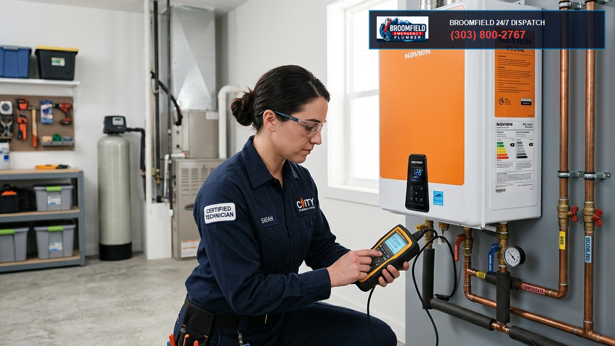
1. The Hydronic Closed Loop: Physics of Fluid Expansion
A closed-loop hydronic heating system is a sealed hydraulic circuit.
Unlike domestic plumbing, which constantly intakes fresh water and expels wastewater down building drains, a hydronic system circulates the exact same water continuously through copper, black iron, or PEX distribution piping.
When water is heated, its molecular kinetic energy increases.
The water molecules bounce vigorously, spreading farther apart.
Consequently, water’s specific volume ($\nu$) increases, and its density ($\rho$) decreases.
The net fluid expansion volume ($V_e$) across a temperature change is calculated using thermodynamic physical principles:
$$V_e = V_s \left( \frac{\nu_2}{\nu_1} – 1 \right) – 3\alpha V_s \Delta T$$
Where:
- $V_s$: Total water volume in the entire hydronic piping, heat exchangers, and terminal fan coils (gallons).
- $\nu_1$: Specific volume of water at initial filling temperature ($ft^3/lb$). At 50°F, $\nu_1 \approx 0.01602 \, ft^3/lb$.
- $\nu_2$: Specific volume of water at peak boiler operating temperature ($ft^3/lb$). At 180°F, $\nu_2 \approx 0.01651 \, ft^3/lb$.
- $\alpha$: Linear coefficient of thermal expansion for the piping material (for carbon steel, $\alpha \approx 6.5 \times 10^{-6} \, \text{in/in/}^\circ\text{F}$; for copper, $\alpha \approx 9.5 \times 10^{-6} \, \text{in/in/}^\circ\text{F}$).
- $\Delta T$: Total temperature rise from fill temperature to operating temperature ($T_2 – T_1$).
In a typical Broomfield commercial facility with 1,500 gallons of system volume heating from 50°F to 180°F, water expands by approximately 3.1 percent.
That represents nearly 47 gallons of extra liquid volume generated out of thin air.
Because liquid water cannot be compressed under normal HVAC operating pressures, if those 47 gallons have no flexible cushion to enter, system pressure increases exponentially.
Pressure will jump from 15 PSI to 40 PSI in seconds.
That is where the expansion tank comes in.
| Component | Engineering Function | Failure Pathology | Catastrophic Consequence |
|---|---|---|---|
| Hydronic Makeup PRV | Reduces high city main pressure (50-90 PSI) to baseline loop fill pressure (12-18 PSI). | Wire-drawn seat, mineral grit under rubber disc, ruptured pilot diaphragm. | Pressure creep forces continuous overpressure, popping safety relief valves. |
| ASME Expansion Tank | Contains a flexible butyl bladder with factory nitrogen pre-charge to absorb expanded water volume. | Bladder perforation, pre-charge gas permeation, corrosion pinhole on air valve core. | Complete waterlogging, total loss of expansion cushion, extreme hydraulic shockwaves. |
| Section IV Relief Valve | Emergency mechanical overpressure release set at 30, 50, or 125 PSI to protect boiler vessel. | Continuous discharge, mineral crystallization on bronze seat, spring fatigue. | Boiler room flooding, loss of treated closed-loop water, dry-fire boiler lockout. |
| RPZ Backflow Preventer | Isolates toxic hydronic boiler water/glycol from Broomfield potable drinking supply. | Check valve fouling, differential relief dump, disc swelling from chloramines. | Potable cross-connection contamination risk, continuous floor discharge. |
| Air Separator / Vent | Strips micro-bubbles of oxygen and nitrogen from heated circulating water. | Float stuck open, float pinned shut by magnetite silt, clogged vent orifice. | Pump cavitation, air-bound radiator coils, rapid internal oxygen corrosion. |
2. ASME Section IV Expansion Tank Sizing & Boyle’s Law
Under ASME Boiler and Pressure Vessel Code (Section IV, HG-709), every closed hydronic heating boiler must be equipped with an appropriately sized expansion tank.
A modern commercial diaphragm or bladder expansion tank contains a flexible synthetic elastomer membrane that divides the steel tank shell into two chambers:
- An air/nitrogen chamber pre-pressurized with gas.
- A water chamber piped directly into the hydronic loop.
The air chamber acts as a spring.
As boiler water heats up and expands, the extra water volume pushes into the tank, deflecting the flexible bladder and compressing the nitrogen pocket according to Boyle’s Law:
$$P_1 V_1 = P_2 V_2$$
The total acceptance volume and total tank size required for an ASME Section IV diaphragm tank are determined by this formula:
$$V_t = \frac{V_e}{\left( \frac{P_a}{P_f} – \frac{P_a}{P_o} \right)}$$
Where:
- $V_t$: Total gross volume of the expansion tank (gallons).
- $V_e$: Net expansion volume of the system fluid (gallons).
- $P_a$: Absolute atmospheric pressure ($PSIA$).
- $P_f$: Initial fill pressure of the system in absolute terms ($P_{\text{fill gauge}} + P_a$).
- $P_o$: Maximum allowable operating pressure at the tank in absolute terms ($P_{\text{relief gauge}} – \text{safety margin} + P_a$).
The Critical Point of Entanglement: Point of No Pressure Change (PONPC)
Where the expansion tank connects to the hydronic loop is known as the Point of No Pressure Change (PONPC).
This is the single physical point in the piping where circulating pump head pressure cannot affect static system pressure.
A fundamental rule of commercial hydronic engineering is: Always pump away from the expansion tank.
When the circulating pump is located downstream of the tank connection, the pump adds its dynamic head pressure to the entire system.
All distribution pipes experience positive gauge pressure, which keeps air vents closed and prevents air entrainment.
If an inexperienced contractor installs the circulating pump pumping into the expansion tank, the pump subtracts its head pressure from the suction side.
Suction pressure can drop below atmospheric pressure.
Automatic air vents suck room air directly into the piping.
The entrained air causes severe cavitation, corrodes steel heat exchangers, and triggers air-binding across upper-floor heating zones.
3. Front Range Atmospheric Physics: Altitude Correction at 5,420 Feet
Broomfield’s elevation of 5,420 feet above sea level introduces atmospheric factors that catch non-local engineers off guard.
At sea level, atmospheric pressure is 14.7 PSIA (29.92 inches of mercury).
In Broomfield, barometric pressure averages only 12.1 PSIA.
That 2.6 PSI difference has a direct mathematical impact on expansion tank sizing calculations and makeup water pressure calibration:
1. Absolute Pressure Shifts Boyle’s Law
Because $P_a$ is 12.1 rather than 14.7, the expansion acceptance ratio changes:
$$\text{Acceptance Ratio} = 1 – \frac{P_f}{P_o} = 1 – \frac{P_{\text{fill, gauge}} + 12.1}{P_{\text{relief, gauge}} + 12.1}$$
If a technician uses standard sea-level tables, the expansion tank will be undersized by 8 to 12 percent for high-volume commercial loops.
2. Static Head Calculations in Multi-Story Buildings
To prevent upper-floor radiators from drawing a vacuum, minimum cold fill pressure must overcome static elevation head plus a 4 to 5 PSI positive pressure cushion at the top fixture:
$$P_{\text{fill}} = (h_{\text{top}} \times 0.433) + P_{\text{cushion}}$$
In a four-story commercial building with 48 feet of elevation between the basement boiler and top-floor perimeter baseboards:
$$P_{\text{fill}} = (48 \times 0.433) + 4.5 = 20.8 + 4.5 = 25.3 \text{ PSI}$$
Notice what happens here!
If the facility has standard 30 PSI boiler safety relief valves, you only have a 4.7 PSI operating window between cold fill (25.3 PSI) and relief discharge (30 PSI).
The slightest temperature expansion will trip the relief valve.
In such Front Range facilities, boilers must be engineered with 50 PSI or 60 PSI ASME Section IV relief valves, and the expansion tank pre-charge must be calibrated accordingly.
4. Forensic Pathology: Why Commercial Boiler PRVs Creep
An automatic boiler feed water pressure reducing valve is designed to do one simple job: maintain a steady, factory-calibrated fill pressure (usually 12 to 15 PSI) inside the hydronic loop.
Under normal conditions, once the closed system is filled and purged of air, the PRV should remain 100 percent closed for months or years.
No new water should ever enter a tight hydronic loop.
Yet in commercial boiler rooms across Broomfield, we regularly find makeup PRVs slowly weeping water into the loop.
This is PRV creep.
Mechanism 1: Mineral Debris & Scale Impingement on the Valve Seat
Broomfield municipal water carries moderate mineral hardness (7 to 12 grains per gallon of calcium and magnesium compounds).
When city water main flushing or neighborhood construction occurs, rust flakes, silica sand, and pipe scale break free from aging iron distribution mains.
If the makeup water line lacks an upstream 100-mesh wye strainer, those mineral particulates travel straight into the PRV body.
As the PRV attempts to close against its internal elastomer seat, a single grain of quartz sand or pipe scale lodges between the rubber disc and the sharp brass seat orifice.
The valve cannot seal tight.
A micro-stream of water continues to pass.
Over eight hours overnight when the heating system is idle, this minute weep raises closed-loop pressure from 15 PSI to 45 PSI, matching static city water pressure.
Mechanism 2: Wire-Drawing of the Metal Orifice
When high-pressure city water (60 to 90 PSI) squeezes through a tiny, partially obstructed opening, fluid velocity spikes dramatically:
$$v = \sqrt{\frac{2 \Delta P}{\rho}}$$
At a 70 PSI pressure differential, water jets through microscopic crevices at speeds exceeding 100 feet per second.
Over weeks of continuous weeping, this high-velocity water jet cuts razor-thin channels directly into the brass or stainless steel seat.
This erosion phenomenon is known as wire-drawing.
Once wire-drawing cuts through the metal seat, the PRV can never seal again.
Even if you clean the rubber disc, water flows through the carved groove around the clock.
Mechanism 3: Thermal Siphonage & Backflow Seal Degradation
If the makeup water connection is piped close to the boiler supply header without an effective thermal trap or check valve, hot hydronic water migrates backward toward the PRV via gravity thermal siphonage.
Commercial makeup PRVs are rated for cold water intake (maximum 120°F).
When 180°F boiler water bakes the PRV’s internal Buna-N or EPDM diaphragm and seat disc, the elastomer hardens, loses elasticity, and cracks.
The cracked disc can no longer hold shut against city water pressure.
5. The Pathology of Expansion Tank Bladder Failure
Why do heavy ASME commercial expansion tanks fail?
A commercial bladder tank looks like an indestructible steel fortress from the outside.
Inside, however, it depends entirely on a flexible synthetic rubber membrane.
1. Nitrogen Gas Permeation Over Time
All elastomer bladders are slightly semi-permeable at a molecular level.
Over three to five years, nitrogen gas molecules slowly permeate through the butyl rubber wall into the water stream, where they are swept away and vented by automatic air separators.
As the gas cushion bleeds away, the pre-charge pressure drops.
If an annual maintenance technician never checks the tank pre-charge, pressure eventually drops from 15 PSI down to zero.
Without gas pressure on the dry side, incoming system water pushes the rubber bladder entirely flat against the top of the steel shell.
The tank is now 100 percent waterlogged. There is zero remaining expansion capacity.
2. Bladder Abrasion & Internal Puncture
When an expansion tank operates under-pressurized, the oversized rubber bladder folds over itself like an accordion during every thermal cycle.
The rough interior surface of an ASME carbon steel tank often develops rust nodules and weld spatter.
As the bladder rubs repeatedly against rough internal steel welds thousands of times per winter, the rubber thins, frays, and develops fatigue punctures.
Once the bladder is punctured, water floods the gas chamber.
Water now touches the raw carbon steel tank wall, initiating severe rust and pinhole exterior leaks through the tank shell.
3. The Vicious Destruction Cycle
PRV creep and expansion tank waterlogging form a deadly positive feedback loop:
- The expansion tank bladder fails, waterlogging the vessel.
- Boilers fire: thermal expansion has nowhere to go. System pressure spikes past 30 PSI.
- The safety relief valve opens, dumping 10 to 30 gallons of treated boiler water onto the floor.
- Boilers cycle off: as the remaining loop water cools, its volume shrinks. Pressure plummets to 0 PSI.
- The low-pressure condition triggers the automatic makeup PRV to open wide, gulping fresh, oxygen-rich city water into the system to restore 15 PSI.
- The boilers fire again, and the cycle repeats 10 to 20 times a day!
This rapid cycling introduces hundreds of gallons of raw, untreated tap water into the closed loop.
The dissolved oxygen inside that fresh water attacks boiler heat exchangers, forming black iron oxide (magnetite) sludge that destroys circulator pump impellers, clogs control valves, and burns out boiler firetubes within months.

6. Real-World Commercial Case Studies Across Broomfield
Our commercial emergency plumbing teams respond to hydronic heating breakdowns 24 hours a day across Broomfield and the Front Range.
Here are six real-world case studies detailing how we diagnosed and corrected complex boiler room emergencies:
Case Study 1: Interlocken Corporate Headquarters Relief Valve Blowout
Facility: An 85,000-square-foot multi-tenant corporate headquarters in Interlocken Technology Park.
The Emergency: At 6:00 AM on a freezing Monday in January (-4°F ambient), the building automation system (BAS) alerted facility engineers that the main heating plant had locked out on high-pressure fault.
The boiler room floor was submerged under three inches of water, and executive suites were rapidly chilling.
Forensic Diagnostic: We arrived on site within 25 minutes.
The heating plant consisted of two 1.5-million-BTU condensing boilers tied to a 100-gallon ASME bladder expansion tank.
We depressed the Schrader air valve on the expansion tank: water shot across the room in a solid stream.
The bladder was torn in half.
Simultaneously, we observed that the makeup PRV was creeping: static loop pressure was sitting at 42 PSI even with boilers shut down.
The Emergency Intervention:
- We isolated the failed expansion tank and drained its 100 gallons of trapped water using submersible pumps.
- We installed a heavy-duty, factory-certified 120-gallon ASME replaceable-bladder tank, pre-charging the nitrogen cell to exactly 18.0 PSI to match the building’s static head.
- We removed the failed makeup PRV and installed a commercial dual-stage pressure reducing manifold with an integrated 100-mesh wye strainer and upstream test gauges.
- We replaced the scorched 50 PSI ASME Section IV relief valve.
- We introduced molybdate corrosion inhibitor chemicals to neutralize oxygen introduced during the emergency.
Outcome: Boilers were re-fired by 9:30 AM. System pressure stabilized at 18 PSI cold and 23.5 PSI hot. Zero office evacuation was required.
Case Study 2: Flatiron Crossing Hospitality Complex Chronic Glycol Loss
Facility: A 180-room full-service hotel near Flatiron Crossing Mall.
The Emergency: Over three months, the hotel mechanical staff had added over \$4,000 worth of propylene glycol to their roof-mounted hydronic snowmelt and perimeter baseboard loop.
There were zero visible leaks anywhere in guest rooms or mechanical chases.
Yet glycol concentration kept dropping from 35% down to 18%, putting roof snowmelt tubing at risk of freezing and splitting.
Forensic Diagnostic: We piped a digital ultrasonic flow meter on the boiler drain lines and connected a data logger to the relief valve discharge pipe.
We discovered that every time the roof snowmelt system activated, loop pressure surged to 32 PSI, causing the safety relief valve to weep into a floor drain hidden behind the air handling units.
Then, as the system cooled, the automatic makeup PRV piped to city water fed fresh water into the loop, diluting the glycol!
The root cause was a severely undersized expansion tank installed during a tenant remodel.
The contractor had sized the tank for plain water, completely ignoring the fact that propylene glycol expands 15% more than pure water across the same temperature range:
$$\nu_{\text{glycol mix}} > \nu_{\text{pure water}}$$
The Solution:
- We calculated the exact fluid volume of the snowmelt and heating circuit (2,100 gallons at 35% glycol).
- We removed the undersized 60-gallon tank and installed dual 100-gallon ASME Section IV bladder vessels manifolded in parallel.
- We installed an automatic glycol feed package with an integrated low-level alarm, physically disconnecting the domestic water makeup PRV to prevent any future unmonitored dilution.
- We recharged the system with inhibited propylene glycol back to 35% concentration (-20°F freeze protection).
Outcome: Loop pressure never exceeded 22 PSI during peak snowmelt firing. Glycol dilution ceased entirely, saving the facility thousands of dollars annually.
Case Study 3: 120th Avenue Senior Living Community Micro-Bubble Cavitation
Facility: A four-story residential assisted living facility in Broomfield.
The Emergency: Residents on the fourth floor complained of loud gurgling, waterfall sounds inside walls, and freezing bedroom fan coils.
The facility maintenance staff had repeatedly bled air from baseboards, but the air returned within forty-eight hours.
Forensic Diagnostic: We checked the location of the circulator pumps relative to the expansion tank.
The circulator pumps were pumping directly toward the expansion tank connection point.
Because the expansion tank was on the pump discharge, the pump’s 18 PSI differential head created a severe suction pressure deficit.
On the fourth floor (42 feet above the boiler room), static water pressure was only 1.2 PSI.
Every time the circulator ramped to high speed, fourth-floor pressure dropped to -2.5 PSI vacuum!
The automatic air vents on the top floor were functioning in reverse: instead of releasing air, they were sucking room air into the hydronic pipes at high speed.
The Solution:
- We re-piped the expansion tank connection directly to the suction side of the primary circulating pumps, establishing the Point of No Pressure Change at pump intake.
- We adjusted the cold fill PRV setpoint from 12 PSI to 22 PSI to maintain a minimum 4.0 PSI positive cushion at fourth-floor radiator vents.
- We installed high-efficiency coalescing micro-bubble air and dirt separators on the hottest boiler discharge lines.
Outcome: The system maintained positive pressure across all floors under all pump speeds. Air entrainment and radiator gurgling ceased permanently.
Case Study 4: Highway 36 Life Sciences Cleanroom PRV Wire-Drawing Catastrophe
Facility: A pharmaceutical development laboratory near US-36 in Broomfield.
The Emergency: High-purity process hot water loops were experiencing uncontrolled pressure fluctuations between 20 PSI and 58 PSI.
High pressure was triggering emergency relief discharges, risking cross-contamination in pristine utility trenches.
Forensic Diagnostic: We isolated the commercial makeup PRV and disassembled its bonnet.
The internal stainless steel valve seat had suffered extreme wire-drawing erosion.
A groove deep enough to catch a fingernail had been sliced across the seat face by high-velocity municipal city water.
The building’s incoming municipal water pressure had recently spiked to 92 PSI following city main booster upgrades.
The single-stage PRV was being forced to drop pressure by 77 PSI in a single step, exceeding the manufacturer’s maximum recommended pressure ratio ($\frac{P_1}{P_2} > 4:1$).
The Solution:
- We installed a two-stage series pressure reducing station: Stage 1 reduces municipal pressure from 92 PSI down to 40 PSI; Stage 2 reduces pressure smoothly from 40 PSI down to 15 PSI.
- We installed a heavy-duty stainless steel pilot-operated control valve with ceramic-coated trim for the secondary stage.
- We installed an electronic high-pressure safety shutoff solenoid valve wired to the BAS to instantly isolate makeup water if loop pressure ever crosses 24 PSI.
Outcome: Two-stage reduction eliminated wire-drawing velocity stresses. Hydronic pressure held dead-stable at 15.0 PSI with zero creep.
Case Study 5: Rocky Mountain Airport Commercial Hangar Thermal Shock
Facility: An aviation charter maintenance hangar at Rocky Mountain Metropolitan Airport.
The Emergency: Following an Arctic cold front, the hangar’s overhead radiant tube hydronic heating system experienced massive thermal shock.
A 3-inch grooved coupling separated in the ceiling trusses, dumping 400 gallons of boiler water over private business aircraft.
Forensic Diagnostic: Our emergency master plumbers discovered the expansion tank bladder had ruptured months prior.
When the massive 40-foot hangar doors opened to admit an arriving jet, ambient temperatures in the hangar plummeted from 68°F to -10°F in two minutes.
The hydronic radiant loops chilled rapidly, contracting fluid volume.
Then, as the hangar doors closed and high-fire burners engaged at 100% capacity, water temperature surged by 120°F in six minutes.
With no air cushion in the waterlogged expansion tank to absorb the volumetric surge, the hydraulic transient shock wave (water hammer) peaked at 88 PSI, shearing the mechanical grooved pipe coupling clean off the ceiling truss.
The Solution:
- We repaired the separated radiant header with heavy-duty structural pipe couplings and rigid sway bracing.
- We installed an oversized 150-gallon ASME Section IV expansion tank with a high-temperature EPDM bladder.
- We installed dual fast-acting mechanical surge relief valves calibrated to bypass high-speed pressure spikes directly to a blowdown tank.
- We calibrated the boiler staging sequence to limit firing ramps to a maximum of 15°F per minute.
Outcome: Destructive hydraulic surges were eliminated, allowing hangar doors to operate without risking heating system structural failures.
Case Study 6: Interlocken Technology Campus Silt-Choked Air Vent Breakdown
Facility: A high-density software engineering office building in Broomfield.
The Emergency: Constant high-pressure alarms on boiler loops accompanied by severe pipe vibration and grinding noises inside variable-speed circulator pump volutes.
Forensic Diagnostic: Due to continuous makeup water feeding through a weeping PRV over two years, massive quantities of dissolved oxygen had entered the black iron piping.
The oxygen reacted with the carbon steel pipe walls, generating kilograms of heavy black magnetite ($Fe_3O_4$) sludge.
The magnetite had migrated into the expansion tank connection line, completely choking the 1-inch tank isolation nipple with rock-hard iron scale.
Although the expansion tank bladder was intact and properly pre-charged, water could not physically enter the tank through the blocked pipe nipple!
The expansion tank was functionally disconnected from the heating loop by iron sludge.
The Solution:
- We cleared and rodded the expansion tank connection manifold, upgrading the pipe diameter from 1 inch to 1-1/2 inches with full-port ball valves.
- We installed a high-capacity magnetic dirt separator equipped with rare-earth neodymium magnets to capture circulating magnetite.
- We executed a chemical hydronic loop flush using neutralizing dispersants to purge over 35 pounds of iron scale from the heating circuit.
- We installed a new makeup PRV and backflow preventer station.
Outcome: Full hydraulic connectivity was restored to the expansion tank. Pump vibration vanished, and loop pressure stabilized under all load swings.
7. Step-by-Step Diagnostic & Recalibration Protocol
Troubleshooting a commercial hydronic heating plant requires systematic diagnostic testing.
Follow this master plumber protocol to safely test and calibrate expansion tanks and makeup PRVs:
Phase 1: Expansion Tank Bladder Integrity Test
- Locate the Schrader air charging valve on the top or bottom of the expansion tank shell.
- Depress the valve core momentarily:
- If liquid water sprays out, the bladder is ruptured. The tank must be isolated, drained, and rebuilt or replaced immediately.
- If pure gas hisses out, the bladder is intact, but the pre-charge pressure must still be measured accurately.
- Critical Rule: You cannot measure tank pre-charge while the tank is connected to pressurized system water! The water pressure will simply press against the bladder, giving a false reading equal to water loop pressure.
- Close the dedicated expansion tank isolation ball valve.
- Open the tank drain valve to dump all water pressure on the wet side of the bladder down to 0.0 PSI. Leave the drain valve open!
- Attach a calibrated digital pressure gauge to the Schrader valve. Measure the dry nitrogen pre-charge.
- Compare pre-charge to calculated design fill pressure:
- If pre-charge is low, use dry nitrogen or clean, oil-free compressed air to pressurize the air chamber until it exactly equals the design cold fill pressure (typically 12 to 18 PSI).
- If the valve stem leaks, replace the Schrader valve core with a high-temperature Viton core.
- Close the tank drain valve and slowly open the tank isolation valve to return the vessel to service.
Phase 2: Makeup PRV Diagnostic & Creep Verification
- Inspect the makeup PRV body for signs of mineral scale crusting or external bonnet weepage.
- Verify that an upstream 100-mesh wye strainer is installed and clean.
- Install a high-resolution 0-60 PSI test gauge directly downstream of the PRV.
- Allow the hydronic loop to cool to ambient temperature (boilers off).
- Close the manual PRV isolation ball valve. Bleed loop pressure down to 10 PSI.
- Open the manual isolation valve: the PRV should open, feed water rapidly, and snap shut cleanly at its setpoint (e.g., 15.0 PSI).
- Leave the system cold and idle for two hours:
- If pressure holds dead-steady at 15.0 PSI, the valve seat is healthy.
- If pressure slowly climbs toward municipal main pressure (25, 35, 50+ PSI), the valve is suffering from PRV creep. Disassemble the valve, clean the seat, replace the rubber disc and diaphragm, or replace the entire PRV assembly.
Phase 3: ASME Section IV Safety Relief Valve Certification
- Inspect the safety relief valve nameplate: verify the set pressure (typically 30, 50, or 125 PSI) and BTU relief capacity match or exceed total boiler gross firing capacity under ASME Section IV rules.
- Inspect the discharge pipe: it must terminate within 6 inches of an open floor drain with an air gap. It must never be threaded, capped, or reduced in diameter.
- Fire boilers to maximum high-fire operating temperature: monitor loop pressure.
- Verify that peak operating pressure remains at least 10% below the safety relief valve setpoint (or at least 5 PSI below for 30 PSI valves).
8. Preventative Maintenance Schedule for Commercial Hydronics
Adhering to this structured maintenance schedule prevents catastrophic boiler room flooding, preserves heating efficiency, and extends the service life of multi-thousand-dollar hydronic equipment:
- Monthly: Visually inspect the boiler room floor, relief valve discharge pipes, and expansion tank shells for water leaks. Check system pressure gauges when boilers are cold and when firing at peak output. Verify pressure rise does not exceed 6 to 8 PSI between cold and hot states. Record makeup water meter reading to detect unmonitored leaks.
- Quarterly: Blow down the 100-mesh wye strainer ahead of the makeup water PRV. Inspect automatic air vents for scale crusting or moisture drips. Test the operation of the low-water cutoff (LWCO) safety control.
- Semi-Annually (Pre-Winter / Mid-Winter): Isolate the expansion tank, drain the wet side to zero, and test nitrogen pre-charge pressure with a calibrated digital manometer. Re-charge with dry nitrogen as required. Manually test-lift the ASME Section IV relief valve lever (if allowed by facility protocol) to clear minor scale deposits from the seat.
- Annually (Comprehensive Master Plumber Audit): Perform professional hydronic water chemistry testing (measure pH, total dissolved solids, glycol concentration, and molybdate/nitrite inhibitor levels). Flush magnetite sediment from dirt separators. Rebuild or replace internal cartridges on commercial makeup PRVs. Certified differential testing of the ASSE 1013 RPZ backflow preventer on the makeup supply line.
Need Emergency Commercial Boiler Hydronic or Expansion Tank Repair in Broomfield?
Is your commercial boiler safety relief valve blowing scalding water across your mechanical room? Is your expansion tank waterlogged, or is your hydronic makeup PRV creeping and overpressurizing your heating loop?
Call Broomfield’s commercial boiler plumbing emergency specialists at (303) 647-3363. Our licensed master plumbers carry replacement ASME Section IV bladder expansion tanks, calibrated commercial makeup PRV manifolds, ASME relief valves, and mobile closed-loop chemical flush trailers to protect your facility 24 hours a day, 7 days a week.