
Table of Contents: Temperature & Pressure (T&P) Relief Valve Engineering Guide
- 1. Executive Summary: The Primary Safety Device Preventing Water Heater Explosions
- 2. Thermodynamics of BLEVE Explosions: Superheated Water & Steam Expansion Physics
- 3. Dual-Action Mechanical Anatomy: ASME A112.4.1 / ANSI Z21.22 Standards & Bi-Metal Probes
- 4. Differential Diagnostics: Thermal Expansion vs. Runaway Overheating vs. Valve Failure
- 5. Closed Plumbing Systems & Thermal Expansion Tank Physics: Boyle’s Law & Water Hammer
- 6. International Plumbing Code (IPC) Discharge Piping Mandates: Materials & Air Gaps
- 7. Comprehensive Diagnostic Failure Matrix: Observable Symptom vs. Mechanical Root Cause
- 8. Step-by-Step Master Plumber Replacement & Pressure Calibration Protocol
- 9. Colorado Front Range Submarket Profiles: High Municipal Pressures & Hard Water Scaling
- 10. Financial Risk Analysis: $300 Preventative Valve Service vs. $65,000 BLEVE Disaster
- 11. Comprehensive Extended FAQ Section (12 Detailed Engineering Questions)
- 12. 24/7 Emergency Water Heater Pressure Relief Services
1. Executive Summary: The Primary Safety Device Preventing Water Heater Explosions
Inside the utility closet, finished basement, or mechanical room of every residential home across the Colorado Front Range sits a heavy cylindrical steel pressure vessel holding 40 to 80 gallons of scalding domestic water. Operating continuously under 50 to 85 pounds per square inch (PSI) of municipal hydraulic pressure and heated by 40,000 BTU natural gas burners or 4,500-watt electric resistance elements, a residential storage water heater contains immense potential energy. The single mechanical apparatus standing between safe, comfortable domestic hot water and a catastrophic, rocket-like structural explosion is the Temperature and Pressure (T&P) Relief Valve.
Engineered to meet rigorous ASME Boiler and Pressure Vessel Code (Section IV) and ANSI Z21.22 / CSA 4.4 standards, the T&P relief valve is an automated, fail-safe electromechanical safety device. Threaded directly into the top spud or upper side shell of the water heater tank within the top 6 inches where water reaches its peak thermal density, the valve is calibrated to open automatically under either of two critical emergency conditions: if internal water temperature reaches 210°F (99°C) or if internal hydraulic pressure reaches 150 PSI (1,034 kPa).
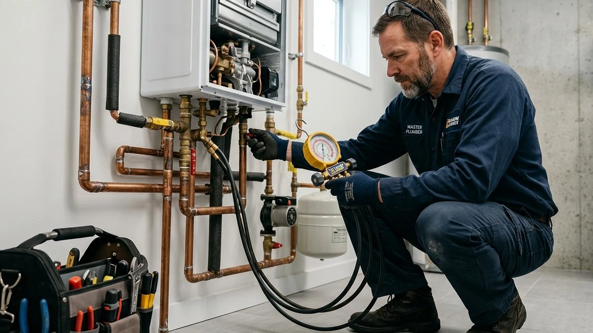
Tragically, when a homeowner notices water intermittently dripping, weeping, or steadily discharging from the bottom of the T&P drain line, their instinct is often to view the symptom as an annoying plumbing leak rather than an urgent cry for help from a stressed pressure vessel. Some homeowners even commit the catastrophic, potentially fatal error of screwing an iron cap onto the end of the discharge line or plugging the valve port with a brass plug to stop the puddle!
Capping, plugging, or neglecting a discharging T&P valve disables the only emergency safety release mechanism on a closed pressure vessel. If the water heater’s primary thermostat welds closed in a runaway heating cycle, superheated water inside a capped tank can undergo an explosive physical phase change known as a Boiling Liquid Expanding Vapor Explosion (BLEVE). The resulting blast possesses enough explosive kinetic energy to blast an 80-gallon water heater straight through two floors of living space, demolish load-bearing roof trusses, and level residential framing. This definitive technical engineering guide breaks down the thermodynamics of superheated steam, closed-loop thermal expansion physics, IPC discharge piping codes, and diagnostic remediation protocols across Broomfield, Westminster, Thornton, and Denver Metro.
Beyond structural catastrophe, chronic minor weeping from a relief valve indicates unmitigated mechanical stress on your entire residential plumbing network. When a relief valve is forced to open repeatedly due to thermal expansion or failed pressure regulation, every fixture in your home—including ceramic cartridge faucets, washing machine supply hoses, dishwasher solenoid valves, and reverse osmosis filter housings—is exposed to extreme hydraulic spikes. Over time, these cyclic pressure surges degrade rubber o-rings and solder joints, culminating in concealed behind-wall leaks and structural mold infestations. Understanding the root cause of relief valve discharge is essential for protecting both human life and property integrity.
2. Thermodynamics of BLEVE Explosions: Superheated Water & Steam Expansion Physics
To comprehend why a dripping T&P valve demands immediate master plumber evaluation, one must examine the extreme thermodynamics of pressurized liquid water. Under normal open-air atmospheric pressure at Colorado’s baseline altitude of 5,400 feet (where barometric pressure is approximately 12.2 PSI instead of sea level’s 14.7 PSI), water boils and converts to vapor at approximately 202°F to 203°F.
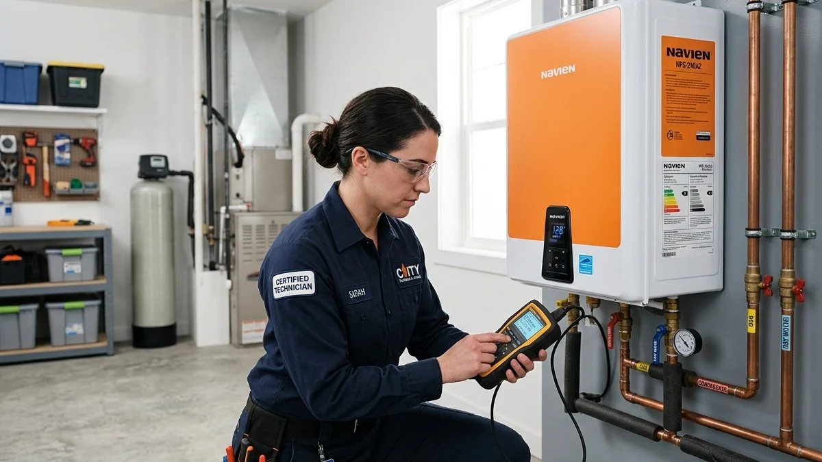
The Pressure-Boiling Point Relationship
Inside a sealed residential water heater operating under 70 PSI of municipal pressure, water cannot boil at 203°F or even 212°F. Under elevated pressure, the boiling temperature shifts upward according to the Clausius-Clapeyron Relation:
At 150 PSI of internal hydraulic pressure, water remains in a liquid state all the way up to 366°F (185.5°C)! This state is known as superheated water. The liquid contains an astronomical quantity of stored thermal internal energy, but the crushing external pressure prevents the water molecules from breaking free into vapor.
The BLEVE Phase Change & Kinetic Blast Energy
If the tank’s steel shell ruptures under pressure while holding superheated 330°F water, the internal pressure drops from 150 PSI to atmospheric pressure in milliseconds. Instantly, the superheated water finds itself more than 125°F above its boiling point! The entire mass of liquid undergoes instantaneous flashing into steam:
One cubic foot of liquid water instantly expands to occupy over 1,600 cubic feet of atmospheric steam! In a standard 50-gallon water heater, this explosive expansion releases approximately 2.5 to 3.5 Million Foot-Pounds of kinetic energy—the thermodynamic equivalent of detonating multiple sticks of commercial dynamite!
The concave steel bottom of the tank inverts violently like a pneumatic piston, shearing the perimeter weld. The tank shell becomes a rocket, rocketing upward through floor joists, second-story bedrooms, and launching through the roofline hundreds of feet into the sky. The T&P relief valve is the single engineered mechanical barrier specifically designed to vent pressurized fluid before this thermodynamic threshold is ever reached.
In municipal testing conducted by mechanical engineering safety councils, unvented 50-gallon water heaters subjected to simulated thermostat failure reached pressures in excess of 330 PSI before cataclysmic tank rupture. In every test case without an operable T&P valve, the resulting shockwave demolished simulated two-story residential wood-framed structures, scattering debris across a 150-foot radius. This is why plumbing inspectors, structural engineers, and fire marshals treat relief valve compliance with zero tolerance.
3. Dual-Action Mechanical Anatomy: ASME A112.4.1 / ANSI Z21.22 Standards & Bi-Metal Probes
A certified T&P relief valve is a marvel of dual-action mechanical redundancy. Unlike standard pressure-only safety valves used on air compressors or boilers, a residential water heater relief valve responds independently to two entirely distinct physical stimuli: thermal expansion and hydraulic pressure.
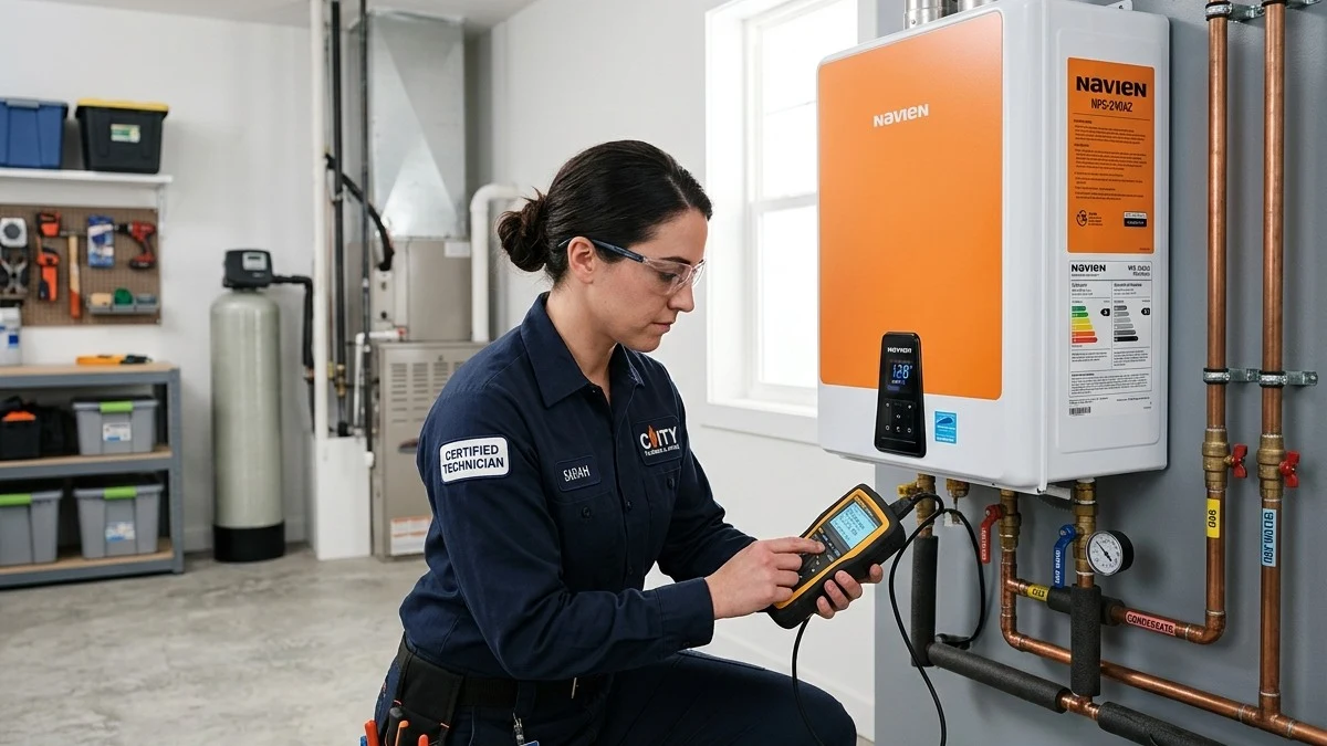
1. The Thermal Sensing Element: Thermostatic Wax Capsule
Extending from the base of the brass valve body down into the hottest upper quadrant of the water heater tank is an elongated copper probe (typically 4 to 8 inches long). Inside the tip of this probe sits a hermetically sealed thermostatic capsule containing an engineered blend of refined microcrystalline petroleum waxes and powdered copper.
When surrounding water temperature reaches 205°F to 210°F, the wax undergoes a solid-to-liquid volumetric phase change. The expanding wax pushes a polished stainless steel piston rod upward through the center of the valve. This mechanical rod physically pushes the sealing disc off its seat, allowing superheated water to vent safely down the discharge pipe, cooling the tank with incoming cold water long before flashing steam temperatures can occur.
2. The Pressure Sensing Element: Calibrated Compression Spring
Completely independent of the thermal wax probe, the upper chamber of the valve contains a heavy-duty, stainless steel or silicon bronze helical compression spring calibrated under ASME Section IV standards. The spring holds an elastomeric silicone or EPDM sealing washer firmly clamped against a machined brass seat under a mechanical pre-load equal to 150 PSI of fluid resistance.
If internal hydraulic pressure rises past 150 PSI (even if water temperature is a safe 120°F), the hydraulic force acting against the underside of the sealing disc overcomes the spring’s mechanical tension ($F = P \times A$). The disc lifts, venting water until pressure drops safely below 125 PSI, at which point the spring snaps the disc shut.
Every certified valve features an exterior aluminum identification plate stamped with its ASME rating, temperature relief rating (typically 210°F / 99°C), pressure relief rating (typically 150 PSI / 1034 kPa), and British Thermal Unit (BTU) steam discharge capacity. Under ANSI Z21.22, the valve’s steam discharge rating (e.g., 105,000 BTU/hr for a standard residential 3/4-inch valve) must strictly equal or exceed the maximum burner or heating element input rating of the water heater itself. If an undersized relief valve is installed on a high-input 199,000 BTU commercial or tankless unit, the valve will choke during a thermal runaway event, creating dangerous backpressure inside the vessel.
4. Differential Diagnostics: Thermal Expansion vs. Runaway Overheating vs. Valve Failure
When a T&P valve is observed dripping or blowing water, master diagnostic plumbers perform forensic testing to categorize the discharge into one of three distinct mechanical root causes:
Scenario A: Intermittent Drip During Heating Cycles (Thermal Expansion)
If the valve only weeps water while the burner is actively firing or shortly after a heavy hot water draw (e.g., showers or laundry), but stops dripping once heating ceases, the valve itself is usually working perfectly! This symptom indicates that the home has a closed plumbing system without a functioning thermal expansion tank. As cold water heats from 40°F to 120°F, it expands physically. Trapped inside rigid pipes with nowhere to go, internal pressure spikes to 150 PSI, causing the T&P spring to burp open to protect the plumbing fixtures.
Master plumbers confirm this diagnosis by attaching a specialized recording pressure gauge equipped with a “lazy hand” peak indicator needle to a laundry bib or drain valve. During the burner cycle, the homeowner will watch the black gauge needle climb steadily from 60 PSI past 100, 120, and peak precisely at 150 PSI right as the valve weeps a small burst of water. Once hot water is run at any sink, the pressure drops instantly back to 60 PSI.
Scenario B: Violent Sizzling Discharge of Steam & Boiling Water (Thermal Runaway)
If the valve discharges roaring, vaporous steam and boiling water at high velocity accompanied by severe rumbling inside the tank, the system is in an active thermal runaway emergency! The primary thermostat has failed in the closed position, and the secondary ECO (Emergency Cut-Off) high-limit switch failed to trip. Homeowners must immediately shut off the natural gas or electric breaker from a safe distance and call for emergency plumbing service.
Scenario C: Constant, Continuous 24/7 Trickle (Mineral Scale or Seat Wear)
If the valve drips constantly around the clock regardless of whether the water heater is heating or resting, the valve’s internal sealing washer has been ruined. In Front Range communities with hard water (8 to 12 grains per gallon), calcium carbonate crystals plate onto the brass seat. When the valve lifts even slightly, sharp mineral grit wedges under the silicone seal, preventing it from reseating.
Additionally, constant weeping can be caused by unmitigated municipal main pressure spikes. If the whole-house Pressure Reducing Valve (PRV) fails, municipal pressure exceeding 150 PSI will continually force the valve off its seat. Testing static water pressure during non-heating periods immediately differentiates between mineral seat fouling and whole-house PRV breakdown.
5. Closed Plumbing Systems & Thermal Expansion Tank Physics: Boyle’s Law & Water Hammer
In modern residential construction across Broomfield, Westminster, and Thornton, every plumbing system is legally classified as a Closed Plumbing System. This closure occurs because municipal water departments require backflow preventers, check valves, or Pressure Regulating Valves (PRVs) installed at the property entry to protect the public water main from contamination.
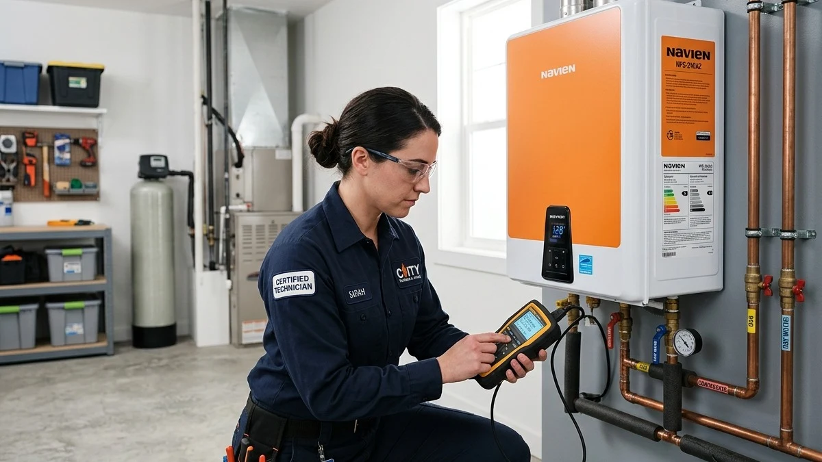
The Incompressibility of Liquid Water & Volumetric Thermal Expansion
Liquid water is chemically incompressible for all practical residential plumbing applications. When a 50-gallon water heater fills with cold 40°F winter groundwater and heats it to 125°F, the thermal volumetric expansion coefficient ($\beta$) causes the water to expand physically by approximately 2.0% to 2.5% in total volume:
Where does this extra gallon of water go? In an older “open” system, the expanding water simply pushed backward into the city main. In a modern “closed” system, the PRV’s internal check valve blocks backflow. Because copper and PEX pipes cannot expand, this trapped volume forces internal pressure to skyrocket from 60 PSI to 150+ PSI in under 12 minutes of burner run-time!
Boyle’s Law & Expansion Tank Pneumatics
To absorb this expansion, plumbing codes mandate the installation of a Diaphragm Thermal Expansion Tank (such as Amtrol Therm-X-Trol ST-5). The tank contains a flexible butyl rubber diaphragm separating household water from a pressurized air cushion. Under Boyle’s Law ($P_1 V_1 = P_2 V_2$), the expanding water pushes against the flexible rubber bladder, compressing the air cushion and keeping total household pressure safely capped below 75 PSI, protecting the T&P valve from premature fatigue.
When an expansion tank fails—typically after 5 to 7 years when the internal rubber bladder perforates and the chamber fills with water—the system loses its compressible air buffer. The moment hot water expands or a fast-acting solenoid valve (such as an ice maker or washing machine) snaps shut, dramatic hydraulic shockwaves known as Water Hammer ripple through the plumbing. Peak transient pressure spikes during water hammer events can exceed 250 to 300 PSI for several milliseconds, stressing pipe hangers, splitting supply lines, and forcing the T&P valve to burp continuously.
6. International Plumbing Code (IPC) Discharge Piping Mandates: Materials & Air Gaps
A T&P relief valve is useless—and potentially hazardous—if its discharge piping is installed improperly. Under International Plumbing Code (IPC Section 504.6) and Uniform Plumbing Code (UPC Section 608.5), the discharge pipe must adhere to rigid safety parameters:
- Full Nominal Diameter: The discharge pipe must match the full internal diameter of the valve outlet (typically 3/4-inch nominal). It must never be necked down, reduced in size, or fitted with restrictive bushings.
- Approved Rigid Metallic / Temperature-Rated Materials: The discharge line must be constructed from rigid materials rated for 210°F and 150 PSI: Type L or M rigid copper, CPVC, or galvanized steel. Standard PVC pipe, garden hoses, and non-certified flexible tubing are strictly ILLEGAL; standard PVC softens and collapses into a rubbery mass at 140°F, trapping superheated water!
- Continuous Downward Pitch: The pipe must maintain a continuous downward slope by gravity, with zero uphill sags or traps where standing water could pool, freeze, or cause mineral scale corrosion inside the pipe.
- No Shutoff Valves or Tee Connections: No valve, tee, union with restrictive orifices, or obstruction of any kind may be installed in the discharge line between the relief valve and its terminal discharge point.
- Unthreaded Terminal Discharge: The end of the pipe must be unthreaded or cut clean. Having threads at the discharge point is a code violation because it tempts untrained individuals to screw on a cap, hose, or plug.
- Air Gap Clearance: The discharge pipe must terminate between 2 inches and 6 inches above the floor, waste receptor, or floor drain pan. This visible air gap prevents back-siphonage of contaminated sewage into the water supply and provides immediate visual evidence if the valve is discharging water.
- Discharge Location Mandates: In finished basements without floor drains, the discharge line must be piped indirect to an approved exterior location terminating 6 to 24 inches above grade pointing down, or into an indirect waste receptor with an air gap. Discharging directly into crawl spaces or living areas is strictly prohibited.
7. Comprehensive Diagnostic Failure Matrix: Observable Symptom vs. Mechanical Root Cause
The comparative diagnostic matrix below assists homeowners and technicians in identifying specific T&P valve failure modes:
| Observable Discharge Symptom | Underlying Mechanical Root Cause | Hazard Severity Level | Required Professional Action |
|---|---|---|---|
| Intermittent drip only during heating cycles | Thermal expansion in closed system; waterlogged expansion tank bladder. | Moderate: Chronic pressure fatigue on plumbing joints. | Test expansion tank Schrader valve; recharge air bladder or replace failed tank. |
| Constant steady 24/7 weeping/drip | Calcium carbonate mineral crust on valve seat or degraded EPDM disc seal. | Moderate: Water waste (hundreds of gal/week); mineral buildup. | Isolate water heater, drain top 5 gallons, replace T&P valve with certified ASME unit. |
| Violent blowing of boiling water & steam | Thermal runaway; welded thermostat contacts; failed high-limit ECO cutoff. | CRITICAL: Extreme explosion & scalding burn hazard. | Kill fuel/power immediately from safe distance; emergency master plumber dispatch. |
| Continuous high-pressure cold/warm flow | Failed municipal Pressure Reducing Valve (PRV) allowing 120+ PSI main pressure. | High: Whole-house fixture damage and washing machine hose bursts. | Test static municipal pressure with gauge; replace failed whole-house PRV. |
| Discharge pipe vibrating or shuddering | Severe water hammer resonance and cavitation during rapid burner ignition cycles. | Moderate: Mechanical loosening of copper joints and solder fatigue. | Install water hammer arrestors; secure loose piping with heavy-duty copper split-ring hangers. |
8. Step-by-Step Master Plumber Replacement & Pressure Calibration Protocol
Replacing a defective T&P relief valve requires precise technical execution and calibration to restore structural safety:
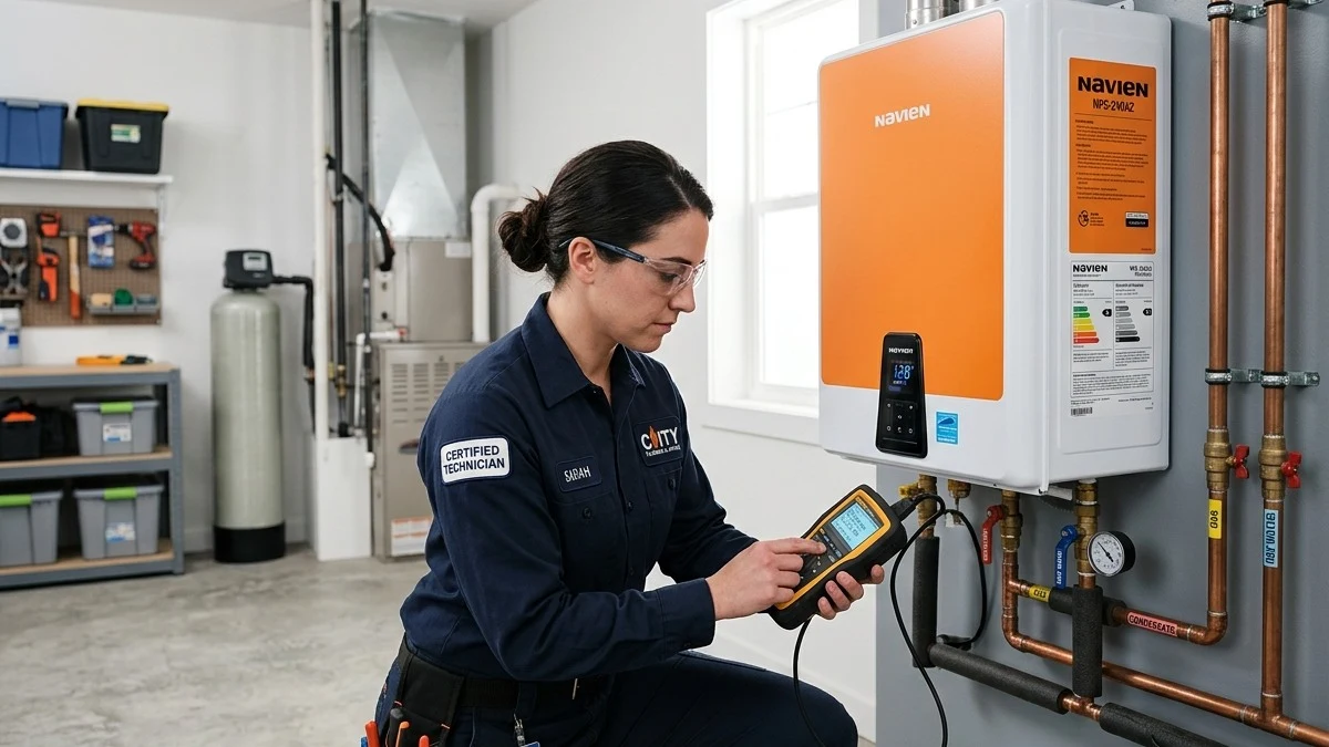
- Energy Isolation & Thermal Safety Depressurization:
Switch off the electric breaker or rotate the gas control valve to “OFF”. Allow the water heater to cool. Shut off the cold water inlet supply valve. Open a hot water faucet upstairs to break vacuum, then connect a transfer hose to the bottom tank drain and drain out approximately 5 to 10 gallons of water to lower the water line below the T&P port.
- Discharge Line Disconnection & Valve Removal:
Disconnect the 3/4-inch copper discharge line at the valve union or unthread the vertical drop. Using a heavy pipe wrench or large adjustable wrench, unthread the old T&P valve counterclockwise from the tank spud. Inspect the female steel threads of the tank spud for corrosion, rust flakes, or calcified scale.
- Probe Calibration & Thread Preparation:
Verify that the replacement valve matches the exact BTU rating of the water heater (the valve’s AGA/ASME rating plate must exceed the input rating of the appliance). Clean the female spud threads with a wire brush. Wrap the male 3/4-inch NPT threads of the new valve with 4 to 5 wraps of heavy-duty gas/water PTFE Teflon tape, followed by an even coating of non-hardening Teflon pipe thread sealant paste.
- Torque Installation & Discharge Reconnection:
Thread the new valve into the spud by hand until snug. Torque the valve body clockwise with a wrench until tight and the discharge outlet faces directly downward (typically 2 to 3 full wrench turns past hand-tight). Reconnect the rigid copper discharge pipe, ensuring a continuous downward slope terminating 2 to 6 inches above the floor drain with an unthreaded end.
- Expansion Tank Pre-Charge Pressure Matching:
Measure static municipal water pressure at an outdoor hose bib or laundry sink with a calibrated liquid-filled pressure gauge (e.g., 60 PSI). Disconnect or depressurize the thermal expansion tank and test its internal air bladder via the Schrader valve. Using a manual bicycle pump or air compressor, charge or discharge the air bladder to match incoming static water pressure within +/- 1.0 PSI. An improperly charged expansion tank cannot absorb thermal expansion!
- Hydrostatic Proof Testing & Air Bleed:
Reopen the cold water supply valve. Keep hot faucets open upstairs until all trapped air escapes in a steady, bubble-free stream. Close faucets and pressurize the tank to full municipal pressure. Inspect the T&P threads for leaks. Fire the burner, allow the water to reach operating temperature (120°F), and verify zero weeping from the new valve discharge line.
- Long-Term Maintenance & Annual Operational Verification:
Document the installation date on the water heater shell with an inspection tag. Instruct the homeowner on annual visual inspections and establish a preventative maintenance schedule to verify thermal expansion tank pressure every 12 months. Routine inspection prevents unexpected high-pressure surprises and ensures 100% mechanical reliability.
9. Colorado Front Range Submarket Profiles: High Municipal Pressures & Hard Water Scaling
Operating conditions across the northern Denver metropolitan corridor create intense mechanical stress on water heater safety valves:
- City and County of Broomfield (Anthem, Broadlands, Country Vista): High-pressure municipal distribution mains feeding newer subdivisions in Broomfield routinely deliver pressures between 85 and 115 PSI. In homes where builder-grade PRVs fail after 7 to 10 years, unmitigated city pressure blows T&P valves open constantly. Furthermore, high dissolved mineral content causes rapid calcium crusting on valve seats.
- City of Westminster (Standley Lake, Countryside, Shaw Heights): Westminster draws surface water from Standley Lake and Clear Creek, resulting in moderate water hardness (8 to 11 grains per gallon). Decades of calcium precipitation cause mineral scaling that cakes over the T&P thermal probe, insulating it from the surrounding water and dangerously delaying thermal activation during runaway overheat events.
- City of Thornton (Grange Creek, Woodglen, Yorkborough): Thornton enforces strict closed-plumbing municipal codes. Upgrading water heaters in Thornton requires installing a code-compliant expansion tank and replacing corroded T&P discharge pipes with rigid copper routed to within 6 inches of the mechanical room floor drain.
- Arvada & West Denver (Leyden Rock, Candelas, Olde Town): Because Arvada sits down-gradient from the Rocky Mountain foothills, water mains experience dramatic static pressure fluctuations during seasonal reservoir transfers. Installing heavy-duty, commercial-grade Watts or Apollo T&P valves with matching expansion tanks is essential to prevent chronic valve weeping.
- Lafayette & Louisville (Coal Creek, Indian Peaks, Steel Ranch): Eastern Boulder County communities often exhibit aggressive seasonal variations in municipal delivery pressure due to peak agricultural and suburban irrigation demands. In these neighborhoods, pressure swings between 45 PSI in daytime irrigation peaks to over 110 PSI overnight, rapidly rupturing aging expansion tank bladders and triggering overnight T&P valve blowouts.
10. Financial Risk Analysis: $300 Preventative Valve Service vs. $65,000 BLEVE Disaster
Maintaining a functioning T&P relief valve is an extraordinarily inexpensive insurance policy against catastrophic structural devastation:
| Service / Disaster Category | Estimated Out-of-Pocket Cost | Property Impact & Safety Reality | Value Protection Rating |
|---|---|---|---|
| Professional T&P Valve & Expansion Tank Tune-Up | $280 – $480 | Replaces worn valve, calibrates expansion bladder, verifies code-compliant discharge. | MAXIMUM: 100% explosion protection and leak prevention. |
| Uncontrolled Basement Flooding From Failed Valve | $8,000 – $22,000+ | A severed or stuck-open valve dumps 500+ gallons into finished basement living space. | Severe financial loss, mold remediation, drywall reconstruction. |
| Catastrophic BLEVE Explosion (Capped / Plugged Valve) | $65,000 – $250,000+ (Total structural demolition) | Water heater rockets through roof; destroys framing; life-threatening trauma. | CATASTROPHIC: Complete destruction of residential property. |
11. Comprehensive Extended FAQ Section
Q1: Why is my water heater T&P valve dripping water?
A dripping T&P valve is caused by one of three issues: (1) Thermal expansion in a closed plumbing system where water expands during heating without an operable expansion tank; (2) Excessive municipal water pressure exceeding 150 PSI due to a failed Pressure Reducing Valve (PRV); or (3) Mineral scale deposits caked on the valve seat preventing the rubber seal from closing tight. Identifying whether the drip occurs continuously or only when the burner is running helps determine the root cause.
Q2: Can I put a cap or plug on a leaking T&P discharge pipe to stop the leak?
ABSOLUTELY NEVER! Capping or plugging a T&P valve is extremely dangerous and illegal under every international and local building code. The T&P valve is the sole safety release device preventing your water heater from exploding like a rocket bomb. Capping a leaking valve turns a minor $250 plumbing repair into a life-threatening BLEVE explosion hazard capable of demolishing your entire home.
Q3: How often should I test my water heater T&P valve?
Manufacturers and plumbing safety standards recommend manually testing the T&P valve once a year. Lift the brass test lever halfway up for 3 to 5 seconds to discharge water through the drain pipe, then release it. The valve should snap shut cleanly and stop dripping immediately. If it continues to leak after testing, the valve seat is corroded and requires immediate professional replacement.
Q4: What pipe materials are allowed for the T&P discharge line in Colorado?
Under the International Plumbing Code, the discharge line must be made of rigid, temperature-rated materials approved for 210°F water: Type M or L rigid copper, CPVC, or galvanized steel. Standard white PVC pipe, garden hoses, and non-certified flexible plastic tubing are strictly prohibited because they soften and collapse when exposed to boiling water, trapping superheated pressure inside the tank.
Q5: How far off the floor should the T&P discharge pipe terminate?
The discharge pipe must terminate between 2 inches and 6 inches above the floor, waste receptor, or floor drain. This air gap prevents contaminated water or sewage from siphoning backward into your potable drinking supply and ensures you can immediately see if the valve is discharging water during an overpressure condition.
Q6: How do I know if my thermal expansion tank has failed?
To check your expansion tank, locate the Schrader air valve (similar to a car tire valve) on the top or bottom of the tank. Depress the valve stem briefly with your fingernail. If water squirts out of the air valve, the internal butyl rubber bladder has ruptured, and the tank is waterlogged and must be replaced immediately. You can also tap the tank: a working tank sounds hollow on top and solid on bottom, while a failed tank sounds completely solid and heavy throughout.
Q7: What is the normal operating pressure for a residential plumbing system?
Safe residential plumbing operating pressure is between 50 and 70 PSI. Pressure above 80 PSI violates international plumbing codes and drastically increases the risk of burst washing machine hoses, leaking toilet fill valves, and blown water heater relief valves. If your static pressure exceeds 80 PSI, a whole-house Pressure Reducing Valve (PRV) must be installed or replaced.
Q8: What does it mean when the T&P valve is releasing steam instead of water?
If the valve discharges vaporous steam and boiling water, your water heater is experiencing thermal runaway. The thermostat has failed to shut off the burner or element, and water has exceeded 210°F. Immediately shut off the gas supply or switch off the electric breaker from a safe location and call for emergency plumbing service right away. Do not attempt to touch the water heater.
Q9: Can I replace a T&P valve myself as a DIY project?
While DIY replacement is technically possible, it is not recommended. The replacement valve must precisely match the tank’s BTU rating, thread depth, and pressure rating. Furthermore, applying excessive torque can crack the glass porcelain lining of the tank spud, ruining the water heater. A licensed master plumber ensures safe installation, proper sealant application, and code compliance.
Q10: Why are there no threads permitted at the end of the T&P discharge pipe?
Plumbing codes explicitly prohibit threads on the terminal end of the discharge line to eliminate any possibility of someone screwing a hose, cap, or valve onto the pipe. A capped discharge pipe completely defeats the purpose of the safety device and sets the stage for a catastrophic BLEVE explosion.
Q11: What is the lifespan of a Temperature and Pressure relief valve?
In Colorado’s mineral-rich water conditions, a T&P relief valve has an engineered lifespan of approximately 3 to 5 years. Hard water calcification gradually compromises the internal spring and rubber seal. Preemptively replacing the valve every 5 years or whenever a new water heater is installed guarantees continuous safety and full compliance with insurance guidelines.
Q12: Does homeowner’s insurance cover water damage caused by a leaking T&P valve?
Most homeowner’s insurance policies cover sudden and accidental water damage caused by a failed plumbing valve. However, if an insurance adjuster discovers that the valve had been leaking for months without repair, or that the pipe was capped or modified with unapproved materials like standard PVC or garden hose, the claim can be disputed or completely denied due to homeowner neglect.
12. 24/7 Emergency Water Heater Pressure Relief Services
Is Your Water Heater Relief Valve Leaking or Weeping Water?
Do not ignore a leaking safety valve or risk a catastrophic tank explosion. Our licensed master plumbers provide same-day emergency T&P valve replacement, thermal expansion tank calibration, and high-pressure diagnostics across Broomfield, Westminster, Thornton, and Denver Metro.