
At 3:45 PM on a violent Thursday afternoon in June in Broomfield, Colorado, a severe Rocky Mountain supercell thunderstorm unloads three inches of rain and marble-sized hail in less than forty-five minutes.
Across the five-acre flat roof of a 250,000-square-foot aerospace logistics distribution facility near the Rocky Mountain Metropolitan Airport, the storm creates an immediate structural crisis.
Water is not draining.
Instead, an eight-inch lake of frigid water is ponding across the single-ply TPO roof membrane.
Inside the high-bay warehouse, structural steel bar joists are groaning under thousands of tons of unanticipated hydraulic weight.
The center of the structural roof deck has deflected downward by four and a half inches.
Up above, the building’s engineered **Siphonic Roof Drainage System** has suffered a catastrophic hydraulic induction choke.
Hailstones packed around the primary siphonic roof drains, dislodging the aerodynamic engineered air baffles.
A roaring vortex of air—a high-velocity hydraulic whirlpool—punched down the center of each drain throat.
The full-bore siphonic water column snapped.
Instead of evacuating water at twenty feet per second under negative atmospheric pressure, the dead-flat horizontal piping manifold choked on air bubbles, collapsing into turbulent, sputtering slug flow.
Drainage capacity plummeted by **seventy-five percent** at the exact moment the storm peaked.
Down in the warehouse aisle, a four-inch welded steel siphonic collector pipe running beneath the roof trusses emits a deafening metallic bang.
The violent cyclic pressure pulses—spiking from deep negative vacuum up to positive water hammer—sheared a seismic sway brace, allowing a joint to separate and dumping thousands of gallons of stormwater across rows of multimillion-dollar avionics inventory.
Commercial siphonic roof drainage systems (engineered under **ASME A112.6.9 and IPC Section 1107**) are masterpieces of advanced fluid dynamics. Unlike traditional gravity roof drains that require sloped piping and carry mostly air, siphonic drainage utilizes natural gravity drop to pull an intense negative vacuum. They evacuate massive storm volumes through small-diameter pipes running completely dead-flat beneath the roof deck.
When a siphonic roof drainage system fails to prime or chokes on entrained air, a commercial roof transforms into an aerial retention reservoir.
Because water weighs **62.4 pounds per cubic foot**, six to eight inches of ponded stormwater can exceed building structural live-load limits, threatening catastrophic structural roof collapse.
Let’s dismantle the complex fluid physics, Bernoulli energy grade lines, air baffle aerodynamics, and high-altitude Colorado hail mechanics that govern commercial siphonic roof drainage across the Front Range.
1. Conventional Gravity vs. Engineered Siphonic Roof Drainage
To understand why siphonic systems fail, one must first appreciate how radically they differ from traditional gravity drainage.
Traditional Gravity Roof Drainage (Open-Channel Manning Flow)
Traditional commercial roof drains operate on standard gravity open-channel flow, governed by **Manning’s Equation**:
$$Q = \frac{1.486}{n} \times A \times R_h^{2/3} \times S^{1/2}$$
Where:
- $n$ = Pipe roughness coefficient (0.012 for cast iron, 0.009 for PVC/polyethylene).
- $A$ = Cross-sectional area of water flow ($\text{sq ft}$).
- $R_h$ = Hydraulic radius ($A / P_{wetted}$).
- $S$ = Slope of the horizontal pipe (minimum 1/8-inch or 1/4-inch per foot, 1% to 2%).
In a gravity system, water trickles into the drain bowl, drawing enormous volumes of ambient air down the pipe.
A conventional gravity drain pipe is typically **seventy-five percent air and only twenty-five percent water**.
Because air takes up three-quarters of the pipe, gravity systems require huge pipe diameters (8-inch, 10-inch, or 12-inch mains), continuous downward slopes that consume precious ceiling headroom, and multiple vertical downspouts penetrating the building floor slab every fifty feet.
Engineered Siphonic Roof Drainage (Full-Bore Torricelli Flow)
A siphonic roof drainage system turns conventional plumbing on its head.
It operates on **Full-Bore Siphonic Flow** governed by the **Bernoulli Energy Equation** and **Torricelli’s Law**:
$$v = \sqrt{2 g H}$$
Where:
- $v$ = Fluid velocity through the piping network (ft/sec).
- $g$ = Gravitational acceleration ($32.2\text{ ft/sec}^2$).
- $H$ = Total available vertical head—the vertical drop from the roof deck drain down to the atmospheric discharge point at ground grade (feet).
In a commercial building with a 30-foot roof elevation ($H = 30\text{ ft}$), the theoretical Torricelli velocity is:
$$v = \sqrt{2 \times 32.2 \times 30} = \sqrt{1,932} \approx \mathbf{43.9\text{ ft/sec}}$$
Accounting for pipe friction and fitting losses, actual siphonic operating velocities range between **15 and 25 feet per second (4.5 to 7.6 m/s)**—roughly four times faster than gravity drainage!
Because the pipe carries **100% solid water and zero air**, pipe diameters are reduced by more than half (a 4-inch siphonic pipe easily replaces a 10-inch gravity main).
Even better for commercial architecture, the horizontal collector piping runs **completely flat with zero slope (0.0% grade)** directly beneath the roof deck, allowing massive open warehouse spans without dropped ceiling interference.
| Engineering Parameter | Conventional Gravity Drainage (IPC Section 1106) | Engineered Siphonic Drainage (ASME A112.6.9 / IPC 1107) |
|---|---|---|
| Fluid Flow Regime | Open-channel gravity flow. Core of pipe contains 75% atmospheric air. | Full-bore closed pipe flow. 100% solid water column with zero air core. |
| Horizontal Pipe Slope | Mandatory downward pitch: minimum 1/8″ to 1/4″ per foot (1% to 2% grade). | Completely flat (0.0% grade). Pipe runs dead level along roof trusses. |
| Operating Flow Velocity | Sluggish: typically 3.0 to 6.0 ft/sec (0.9 to 1.8 m/sec). Silt accumulates. | High-velocity self-scouring: 15.0 to 25.0 ft/sec (4.5 to 7.6 m/sec). |
| Internal Hydraulic Pressure | Neutral atmospheric pressure throughout ($P \approx 0\text{ PSIG}$). | Negative sub-atmospheric pressure: -5 to -15 ft of water (-2 to -7 PSIG). |
| Drain Bowl Architecture | Standard open cast-iron dome strainer admitting air and water freely. | Engineered Air Baffle Disc. Physically blocks air entry while admitting water. |

2. The Heart of the System: Air Baffle Mechanics & The Four Priming Phases
How does a siphonic system purge all air from horizontal pipes and establish a full siphonic vacuum?
The secret lies entirely inside the **ASME A112.6.9 Siphonic Drain Bowl Assembly**.
Unlike conventional roof drains that feature a simple open dome grate, a siphonic drain contains a flat, aerodynamic **Air Baffle Plate** positioned horizontally directly above the drain throat.
During a severe rainstorm, the system transitions through **Four Discrete Hydraulic Priming Phases**:
- Phase 1: Gravity Flow (Light Rainfall): Rainfall is light. The water depth on the roof sits below the edge of the air baffle. Water trickles into the drain throat like a standard gravity drain, carrying ambient air with it. The horizontal piping carries open-channel flow.
- Phase 2: Plug / Slug Flow (Rainfall Intensifies): As rainfall increases, the water level on the roof rises until it reaches the outer perimeter rim of the air baffle plate. Water surges into the drain throat in intermittent slugs, trapping pockets of air between advancing water plugs.
- Phase 3: Bubble Flow & Full-Bore Transition: Water depth over the drain reaches **1.5 to 2.5 inches (40 to 65 mm)**, completely submerging the perimeter slots of the air baffle plate. The air baffle acts as a physical hydraulic shield. It blocks atmospheric air from entering the drain throat while drawing solid water smoothly from all 360 degrees of the roof surface. High-velocity water purges remaining air bubbles downstream.
- Phase 4: Full Siphonic Operation (Peak Design Storm): The piping network is 100% full of solid water. The heavy water column falling down the vertical stack creates a powerful **negative siphonic vacuum** behind it. The vacuum travels backward through the dead-flat horizontal collector pipes, literally sucking water off the roof at maximum design velocity ($v > 20\text{ ft/sec}$).
Once Phase 4 is reached, the siphonic drain evacuates water at astronomical rates.
A single 4-inch ASME siphonic drain can evacuate **up to 1,200 gallons per minute**—equivalent to four conventional 6-inch gravity drains!
3. Forensic Pathology: Why Siphonic Drainage Systems Choke & Collapse
If siphonic drainage is so powerful, why do commercial warehouses and corporate facilities across the Front Range suffer catastrophic roof ponding and pipe blowouts?
Because siphonic systems operate on an ultra-precise hydraulic knife-edge: **If air enters the pipe, the entire system collapses.**
Failure Mode 1: Air Baffle Displacement & Vortex Induction Choke
The single most common trigger of siphonic failure is **Air Baffle Damage or Displacement**.
Roofing contractors, HVAC maintenance personnel, or heavy hail storms frequently damage the lightweight cast-aluminum or engineered polycarbonate air baffle disc.
Sometimes, an unqualified roofing technician thinks the baffle is an obstruction and physically removes it!
Without the air baffle:
The moment water reaches four inches of depth, Coriolis force and fluid acceleration create a violent **atmospheric vortex (a draining whirlpool)** in the center of the drain bowl.
The vortex core acts like an open chimney, sucking thousands of cubic feet of atmospheric air straight into the piping.
The continuous water column snaps instantly.
The siphonic vacuum collapses.
The system drops out of high-velocity full-bore flow and reverts to gravity flow.
Because the horizontal pipes have **zero pitch (dead-flat grade)** and small diameters (sized for siphonic velocity, not gravity capacity), the water cannot drain away!
Water backs up across the roof at rates exceeding 50 GPM per un-baffled drain, building lethal ponding loads within twenty minutes.
Failure Mode 2: Negative Pressure Piping Implosion
Siphonic systems generate intense negative pressure.
In tall commercial facilities (such as high-bay distribution centers or multi-story office towers), internal gauge pressure in the horizontal collector manifold drops to **-10 to -22 feet of water column (-4.3 to -9.5 PSIG)**.
External atmospheric air is pushing against the outside of the pipe at 12 to 14 PSI, while the inside of the pipe is under deep vacuum.
If the mechanical contractor installed standard thin-walled PVC (Schedule 40 or DWV) or lightweight galvanized sheet metal instead of engineered **Heavy-Duty High-Density Polyethylene (HDPE with SDR 26 or SDR 17 rating)** or **Schedule 40 Carbon Steel**:
The pipe walls will buckle inward and **implode like a crushed aluminum can**.
Similarly, if mechanical grooved couplings lack engineered internal vacuum gaskets, the negative pressure pulls the gasket lips inward, sucking atmospheric air into the pipe joints and breaking the siphonic prime.
Failure Mode 3: Siphonic Cavitation & Cyclic Hydraulic Shock
In high-rise commercial structures where vertical drop ($H$) exceeds 45 feet, the negative pressure can approach the thermodynamic vapor pressure of water ($P_v$).
When localized static pressure drops below vapor pressure, the water literally boils at ambient roof temperature.
Millions of microscopic vapor cavities form and violently collapse against the pipe walls—a destructive condition known as **Siphonic Cavitation**.
Cavitation generates intense acoustic screeching, violent pipe shuddering, and cyclic pressure spikes that fatigue pipe support hangers.
Without engineered **Seismic Sway Bracing and Rigid Cleat Anchors** (mandated under **ASPE Design Standard 45**), the thrashing pipe breaks free from overhead bar joists, falling into occupied warehouse spaces.
4. Front Range Hail Alley Physics: Hail Dams & Structural Ponding Loads
Broomfield and the Denver-Boulder corridor sit directly in the heart of North America’s notorious **”Hail Alley”**.
Severe severe convective weather produces distinct mechanical threats unique to the Front Range:
The Lethal Physics of Hail Damming
During a severe summer supercell, an intense thunderstorm can dump three to six inches of accumulated hail across a commercial roof in under twenty minutes.
Hailstones float in water.
As torrential rain begins flowing toward the siphonic roof drains, floating hailstones wash along with the current.
The hail packs tightly against the perimeter of the siphonic drain domes, forming a solid, frozen, interlocking slush dam.
The slush dam acts as an impermeable barrier.
Water cannot reach the drain throat!
Stormwater backs up behind the frozen hail dam, submerging vast roof zones under six to twelve inches of water.
Calculating Structural Roof Ponding Loads
Commercial facility managers frequently underestimate the terrifying weight of ponded water.
Water has a physical density of **62.4 pounds per cubic foot ($\text{lbs/cu ft}$)**.
Expressed in terms of roof surface area:
$$\text{Load per Inch of Depth} = \frac{62.4\text{ lbs/cu ft}}{12\text{ inches}} = \mathbf{5.20\text{ lbs/sq ft per inch of depth}}$$
Now, consider a 100,000-square-foot commercial warehouse roof in Broomfield where hail dams cause stormwater to pond to an average depth of **eight inches**:
$$\text{Unit Load} = 8\text{ inches} \times 5.20\text{ lbs/sq ft/in} = \mathbf{41.6\text{ lbs per square foot}}$$
$$\text{Total Roof Weight} = 100,000\text{ sq ft} \times 41.6\text{ lbs/sq ft} = \mathbf{4,160,000\text{ pounds (OVER 2,080 TONS!)}}$$
Over **two thousand tons of unexpected water weight** is suddenly sitting on top of the structural steel trusses!
Most commercial warehouse roofs are engineered for a maximum design live load of **20 to 30 pounds per square foot**.
At 41.6 lbs/sq ft, structural steel bar joists deflect downward.
As the roof sags in the center, it creates a progressive depression that pulls even more water toward the middle—a fatal structural phenomenon known as **Progressive Ponding Instability**.
Without emergency secondary overflow scuppers and immediate siphonic clearing by master plumbers, catastrophic structural roof collapse is inevitable.
5. Secondary Overflow Scuppers & IPC Code Mandates (Section 1108)
Because siphonic systems are vulnerable to hail dams and air baffle blockages, the **International Plumbing Code (IPC) Section 1108 and International Building Code (IBC) Section 1502** strictly mandate **Secondary (Emergency Overflow) Roof Drainage**.
The code requirements are clear and uncompromising:
- 100% Sizing Independence: The secondary overflow drainage system must be sized to handle **one hundred percent of the 100-year, 1-hour rainfall event** completely independently of the primary system. The engineering calculations cannot assume the primary siphonic system is working!
- Separate Discharge Trajectory: Secondary overflow piping cannot connect into the primary siphonic manifold. It must discharge separately to atmosphere in a location where water discharge is **conspicuously visible to building occupants** (such as high-level scuppers discharging with an open waterfall above pedestrian entrance walkways).
- Elevation Offset: Secondary overflow drains or wall scuppers must be installed with their invert elevation set **at least 2.0 inches above the low-point roof drain elevation**, and no higher than the maximum structural water depth permitted by the structural engineer.
6. Real-World Commercial Case Studies Across Broomfield
Here are five forensic field case studies from our Broomfield commercial emergency master plumbing archives:
Case Study 1: Interlocken Aerospace Logistics Facility Hail Ponding Crisis
Facility: A 220,000-square-foot aerospace logistics fulfillment warehouse in Interlocken with an engineered HDPE siphonic drainage system.
The Emergency: During an intense July thunderstorm dumping 2.5 inches of rain and quarter-sized hail, warehouse sensors detected roof truss deflection exceeding three inches. Water was beginning to weep through structural deck weld seams directly above high-value satellite communication components.
Investigation: Our emergency commercial master plumbing crew arrived on site with safety harness rigging.
We accessed the roof under driving rain.
We discovered eight inches of water ponded across the center three bays.
Every single primary siphonic roof drain was surrounded by a solid, packed collar of floating hail and shredded tree leaves.
The hail had packed beneath the air baffle plates, lifting two of the baffles off their mounting studs.
Massive air vortexes were roaring down the center of the drains, choking the siphonic manifold.
The system was operating at barely 20% capacity.
The Solution:
- Our team deployed high-pressure pneumatic air lances and commercial snow rakes to clear the packed hail dams around all sixteen drain bowls.
- We re-seated and securely bolted the dislodged aerodynamic air baffles using stainless steel locking hardware.
- Within four minutes of baffle re-engagement, the system primed into full Phase 4 siphonic mode: an enormous, deep hydraulic roar reverberated through the roof, and the eight-inch ponded lake evacuated completely in under fifteen minutes.
- We cleared blocked parapet overflow scuppers to restore secondary emergency drainage.
Outcome: Structural roof deflection normalized immediately, preventing over $4,000,000 in catastrophic avionics water damage and structural roof collapse.
Case Study 2: Flatiron Retail Anchor Siphonic Manifold Implosion
Facility: A two-story commercial department store near Flatiron Crossing Mall with a 40-foot vertical siphonic drop.
The Emergency: During a cloudburst storm, retail employees on the upper fashion floor heard an explosive crunching noise above the suspended drywall ceiling, followed by torrential stormwater flooding through lighting fixtures.
Investigation: We accessed the ceiling space and discovered twenty feet of 6-inch horizontal siphonic drainage pipe had collapsed inward and torn away from its mechanical couplings.
The original mechanical contractor had installed standard Schedule 40 thin-gauge PVC pipe instead of heavy-duty electrofusion HDPE or Schedule 40 welded steel.
When the 40-foot vertical drop primed into full siphonic velocity ($v > 22\text{ ft/sec}$), internal vacuum plunged to **-18 feet of water head (-7.8 PSIG)**.
The thin PVC pipe could not withstand the external atmospheric pressure, buckling inward and shattering under the vacuum load.
The Solution:
- We removed the shattered PVC run and engineered a replacement high-density polyethylene (HDPE SDR 17) siphonic collector main.
- All joints were welded using automated **ASTM F1055 Electrofusion Couplings**, creating homogenous, leak-proof parent material bonds.
- We installed heavy-duty engineered siphonic guide rail hangers and anti-vibration anchor points to absorb cyclic hydraulic thrust forces.
Outcome: The department store re-opened with an engineered, vacuum-rated drainage infrastructure capable of withstanding full -14.7 PSIG vacuum without deflection.
Case Study 3: Corporate Distribution Center Scupper Ice Dam & Truss Sag
Facility: A major food distribution refrigerated warehouse in Broomfield.
The Emergency: Following an early October blizzard followed by warm sun and rapid snowmelt, the building management system triggered a structural strain-gauge alarm on roof bay C-4.
Investigation: We inspected the parapet perimeter.
Refrozen snow had formed solid ice dams six inches thick across the secondary emergency overflow scuppers.
Meanwhile, on the main roof, melting snow was ponding five inches deep because the primary siphonic drains were frozen solid by sub-zero nighttime temperatures.
The water was trapped on the roof with nowhere to escape.
The Solution:
- We deployed mobile high-output steam generators to melt the frozen ice dams from both primary siphonic bowls and secondary overflow scuppers within 45 minutes.
- We installed self-regulating commercial electric heat trace cables (Raychem) inside all siphonic drain bodies and through the horizontal collector lines.
- We insulated the unheated roof drain bowls with closed-cell elastomeric foam to prevent future freeze-ups down to -30°F.
Outcome: Structural roof load dropped to zero, and the facility maintained continuous cold-storage food delivery operations throughout the winter.
Case Study 4: Data Center Mechanical Penthouse Siphonic Cavitation
Facility: An enterprise financial data center in Broomfield with a critical server hall.
The Emergency: During heavy rains, server room operators felt intense acoustic vibrations vibrating the raised floor tiles and heard a high-pitched screaming sound echoing through utility chases.
Investigation: Our diagnostics team attached digital pressure transducers along the siphonic downspout header.
We discovered severe hydraulic cavitation occurring inside the horizontal collector line directly above the server hall.
The original hydraulic design had oversized the vertical drop stack, causing the water column to fall too rapidly.
Localized internal static pressure in the horizontal pipe was dropping to **-28 feet of water head (-12.1 PSIA)**—reaching the local boiling point of water in Broomfield!
Vapor bubbles were forming and collapsing at high frequency, generating intense shockwaves that vibrated the structural steel joists.
The Solution:
- We re-calculated the system energy grade line and installed an engineered orifice restrictor plate at the base of the vertical drop stack to balance friction losses against available potential energy.
- The restrictor plate raised minimum internal operating pressure to a safe -8 feet of water head, completely eliminating vapor bubble cavitation.
- We added elastomeric acoustic isolation pads to all pipe clamps.
Outcome: Cavitation vanished completely, restoring silent, vibration-free stormwater drainage.
Case Study 5: Aviation Hangar Horizontal Manifold Construction Debris Clog
Facility: A corporate private jet hangar at Rocky Mountain Metropolitan Airport in Broomfield.
The Emergency: During an intense afternoon rainstorm, stormwater began backing up out of the primary siphonic cleanout, overflowing into executive jet maintenance bays.
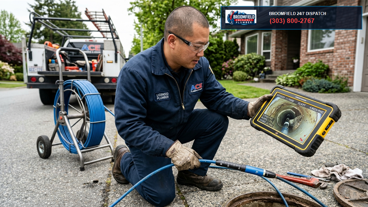
Investigation: We inserted a high-resolution pan-and-tilt sewer camera down the horizontal siphonic collector pipe.
Because siphonic pipes run completely dead-flat (0% slope), any heavy debris that enters the system during construction can settle during light rains.
Forty feet into the 6-inch manifold, our camera revealed a massive obstruction: a 2-foot piece of discarded roofing membrane insulation and several wooden 2×4 shims left behind by roofing contractors months earlier.
The debris had wedged across an elbow fitting.
Under peak storm flow, the debris created an artificial hydraulic choke, preventing full-bore siphonic transition and backing water up onto the hangar roof.
The Solution:
- We deployed our high-flow trailer-mounted hydro-jetting rig operating at 3,500 PSI with a reverse-pulsing rotary nozzle.
- We scoured the entire horizontal dead-flat manifold, flushing all roofing debris and silt into the outdoor catch basin.
- We installed tamper-proof stainless steel lockable dome strainers on all roof drain bowls.
Outcome: Full design siphonic flow was restored, protecting corporate aircraft from water damage.
Case Study 6: Interlocken High-Tech Cold Storage Negative Vacuum Pipe Implosion
Facility: A refrigerated distribution hub operating in Interlocken Business Park, Broomfield.
The Emergency: During an intense convective cloudburst dropping 2.6 inches of heavy rain in 35 minutes, facility engineers heard explosive thuds echoing along the ceiling trusses 28 feet above the main cold storage room.
Moments later, water poured through the ceiling panels onto pallet racks storing temperature-sensitive pharmaceuticals.
The Forensic Findings: Our emergency crew immediately accessed the ceiling interstitial space.
We discovered an 8-inch horizontal collector pipe that had literally imploded.
The pipe walls were crushed inward like an aluminum beverage can.
What happened?
During a previous mechanical upgrade, a non-certified mechanical contractor had replaced a damaged 40-foot section of high-density polyethylene (HDPE) with standard cellular core Schedule 40 PVC pipe.
Cellular core PVC possesses micro-bubble foam inside its core. It is rated exclusively for gravity DWV drainage. It has zero negative pressure vacuum rating.
When the storm hit peak intensity, all six engineered roof drains reached full-bore siphonic priming.
The vertical drop through the 30-foot downspout generated extreme negative pressure inside the horizontal header, reaching -11.4 PSI (-23.2 inches of mercury).
Atmospheric pressure outside the pipe overwhelmed the cellular foam core.
The pipe buckled violently.
When the pipe buckled, the sudden loss of siphonic continuity caused an immediate hydraulic transient shock (water hammer).
The shockwave sheared standard lightweight threaded-rod ceiling hangers, snapping the pipe joint clean open.
The Emergency Intervention:
- Our team deployed high-volume submersible trash pumps on the roof deck to relieve 4 inches of standing water ponding above the cold room bay.
- We cut out the crushed cellular core PVC and purged the remaining system of debris.
- We installed heavy-duty SDR 11 HDPE thick-wall siphonic pipe, fusing every joint with high-amperage electrofusion couplings.
- We installed structural seismic 4-way sway braces every 10 feet along the overhead truss line, engineered to absorb 2,800 pounds of dynamic hydraulic thrust.
- We conducted a full ultrasonic wall thickness scan and negative pressure decay test on the entire header.
Outcome: The system was fully recertified before the next Front Range storm cycle. Pharmaceutical inventory was preserved, and the building owners avoided an estimated \$650,000 structural and stock loss.

7. Step-by-Step Siphonic Drain Inspection & Baffle Tuning Protocol
Servicing and recertifying an engineered siphonic roof drainage system requires specialized master plumber diagnostic procedures:
Phase 1: Roof Deck Drain Bowl & Baffle Audit
- Clear all standing debris, leaves, and silt within a 10-foot radius of every siphonic drain bowl.
- Inspect the aerodynamic air baffle plate. Verify the baffle is firmly secured to mounting studs with stainless steel lock nuts. Verify zero cracks, warpage, or missing perimeter segments.
- Measure the elevation clearance between the underside of the air baffle disc and the drain bowl seating rim with a depth micrometer. Clearance must match engineered manufacturer specifications (typically 1.25 to 1.75 inches). An incorrect clearance gap prevents full siphonic priming!
Phase 2: Horizontal Manifold Joint & Hanger Inspection
- Access interior building ceiling spaces. Inspect the entire dead-flat horizontal collector manifold.
- Verify all seismic sway braces and rigid four-way anchor points are intact without bent threaded rods or cracked structural clamps.
- Inspect electrofusion or mechanical grooved couplings for signs of vacuum elongation, joint slip, or rubber gasket extrusion.
Phase 3: Secondary Overflow Scupper Verification
- Inspect all secondary emergency overflow scuppers through the parapet walls. Verify invert elevation is at least 2.0 inches above primary drain rims.
- Confirm overflow discharge chutes are 100% unobstructed by bird screens, bird netting, or exterior architectural facades.
Phase 4: Simulated Full-Flow Hydraulic Verification
- Where feasible, perform controlled hydraulic flood testing on isolated roof bays using high-volume temporary water trailers.
- Monitor the water depth over the drain bowl as water accumulates: verify Phase 1 (gravity), Phase 2 (slug), and Phase 3 (submerged baffle) transitions occur smoothly.
- Observe the sudden transition into Phase 4 (full siphonic roar). Measure negative vacuum pressure at test taps to confirm full-bore priming.
8. Preventative Maintenance Schedule for Commercial Siphonic Roofs
Adhering to this disciplined preventative maintenance schedule prevents catastrophic structural roof ponding:
- Monthly (During Storm Season: April – October): Inspect all roof drain bowls. Clear leaves, windblown trash, and sediment. Verify all air baffle plates are intact and firmly bolted down. Inspect parapet overflow scuppers.
- Immediately After Every Severe Hailstorm: Emergency inspection of all roof drains. Break apart and shovel away packed hail dams around drain bowls. Verify hailstones have not cracked brittle polycarbonate baffle plates.
- Quarterly: Inspect horizontal siphonic collector piping inside ceiling trusses. Check seismic sway braces and rigid anchors for loose bolts or structural deflection. Check cleanout plugs for positive seal.
- Annually (Pre-Winter: October): Inspect and test electric heat trace cables on siphonic drains and horizontal collectors. Clear secondary overflow scuppers of any accumulated dirt. Run high-resolution camera inspections down horizontal manifolds to verify zero construction debris or silt accumulation.
Need Emergency Commercial Siphonic Roof Drainage or Roof Ponding Service in Broomfield?
Is stormwater ponding dangerously on your commercial warehouse roof? Have hail dams choked your siphonic drains, or is a horizontal collector pipe vibrating under severe vacuum pulses?
Call Broomfield’s commercial plumbing emergency specialists at (303) 647-3363. Our certified master plumbers carry replacement ASME siphonic air baffles, electrofusion HDPE welding equipment, high-volume hydro-jetting trailers, and emergency roof water extraction pumps to protect your facility 24 hours a day, 7 days a week.