
At 2:30 AM on a Sunday morning inside an empty four-story corporate office building in Interlocken in Broomfield, Colorado, a tiny brass bypass orifice measuring fifteen-thousandths of an inch clogs shut.
Up on the third-floor men’s restroom, a single commercial chrome flushometer valve was flushed at 11:00 PM Saturday night by a late-working tenant.
The valve opened smoothly.
It never closed.
For three and a half continuous hours, pressurized municipal water has been roaring out of that 1-inch valve throat at **forty gallons per minute**.
By 2:30 AM, over **eight thousand four hundred gallons of water** have surged down the vitreous china bowl.
When paper towels accidentally drop into the toilet, the trapway chokes.
The water surcharges over the porcelain rim.
A two-inch lake forms across the commercial restroom tile, cascades under the privacy stall partitions, breaches the hallway threshold, and pours down the central elevator shaft.
Down on the ground floor, water begins raining through acoustic ceiling tiles into executive boardrooms, drenching server racks, and tripping main circuit breakers.
Commercial flushometer valves (commonly branded as Sloan, Zurn, American Standard, or Delany) are marvels of mechanical and hydraulic engineering. Unlike residential gravity-tank toilets that rely on stored water and flappers, commercial flushometers connect directly to high-pressure domestic water mains. They deliver an explosive, high-velocity hydraulic pulse capable of evacuating heavy commercial waste in less than five seconds.
When a flushometer valve fails into a continuous open run, it is not a slow drip.
It is an open firehose inside a public restroom.
Understanding why flushometer valves stick wide open, why upper chambers fail to re-pressurize, how piston mechanisms compare against elastomeric diaphragms, and how porcelain siphon jets clear waste requires deep mastery of fluid dynamics, Bernoulli pressure gradients, and Front Range municipal water chemistry.
Let’s dismantle the mechanical physics of commercial flushometers, diagnose continuous dumping pathologies, review Water Supply Fixture Unit (WSFU) flow calculations under the **International Plumbing Code (IPC)**, and examine certified master plumber troubleshooting protocols.
1. The Hydraulic Physics of the Flushometer Cycle (Bernoulli Equilibrium)
How does a commercial flushometer open wide, deliver precisely 1.28 or 1.6 gallons of water, and automatically shut off against 60 PSI of line pressure without using an electrical motor or external timing clock?
The entire mechanism operates on pure hydraulic pressure differentials governed by **Bernoulli’s Principle** and force-area imbalances.
Inside the chrome-plated cast brass valve body sit two primary chambers:
- The Lower Inlet Chamber: Connects directly to the pressurized building water main via the 1-inch control stop valve.
- The Upper Pressure Chamber: Located directly beneath the removable brass bonnet cap, sealed from the lower chamber by a flexible elastomeric diaphragm or sliding piston assembly.
A microscopic bypass channel connects the lower chamber to the upper chamber.
The Force-Area Equilibrium at Rest
When the flushometer is resting between flushes, pressurized water flows through the bypass channel until the upper chamber fills completely.
At static rest, the water pressure inside both chambers is completely equal:
$$P_{upper} = P_{lower} = P_{line} \approx 60\text{ PSIG}$$
Why does the valve stay closed if pressures are identical?
Because of **Surface Area Differential**.
The effective surface area on top of the diaphragm ($A_{upper}$) is the entire circular diameter of the valve bonnet (approximately 7.0 square inches).
The effective surface area on the bottom of the diaphragm ($A_{lower}$) is restricted to the narrow annular ring surrounding the center discharge barrel (approximately 4.2 square inches).
Applying the fundamental force equation ($F = P \times A$):
$$F_{downward} = P_{line} \times A_{upper} = 60\text{ PSI} \times 7.0\text{ sq in} = \mathbf{420\text{ pounds}}$$
$$F_{upward} = P_{line} \times A_{lower} = 60\text{ PSI} \times 4.2\text{ sq in} = \mathbf{252\text{ pounds}}$$
A net downward hydraulic force of **168 pounds** ($420 – 252 = 168\text{ lbs}$) clamps the rubber diaphragm tightly against the polished brass main valve seat.
The valve is held shut by the very pressure of the water it is holding back.
The Dynamic Actuation & Reset Cycle
When a building occupant pushes the chrome handle:
- The internal handle plunger pushes against the tilt-action relief valve stem in the center of the diaphragm.
- Tilting the stem opens a wide relief port, venting the pressurized water in the upper chamber straight down into the bowl discharge tube.
- Instantaneously, $P_{upper}$ crashes to near-zero ($0\text{ PSIG}$).
- Because $P_{lower}$ remains at 60 PSIG, the upward hydraulic force ($252\text{ lbs}$) effortlessly blasts the diaphragm upward off the brass seat.
- Pressurized water rushes into the bowl at **35 to 45 gallons per minute**, surging through the rim jets and siphon jet nozzle.
- As the handle returns to center, the relief valve stem reseats.
- Water immediately begins trickling back into the upper chamber through the microscopic **0.015-inch bypass orifice**.
- Over four to seven seconds, the upper chamber refills. As $P_{upper}$ approaches line pressure, the force-area imbalance re-establishes, driving the diaphragm smoothly back down onto its seat and concluding the flush cycle.
2. The Primary Failure: 0.015-Inch Bypass Orifice Clogging
Why does a flushometer valve stick open and run continuously?
In over eighty percent of commercial service calls, the root cause is a microscopic obstruction in the **Bypass Orifice**.
The bypass orifice is a precision-machined pinhole in the diaphragm or piston body measuring **0.015 inches (0.38 millimeters)** in diameter—roughly the thickness of four human hairs.
Consider what happens when that pinhole clogs:
When the user flushes, the upper chamber dumps water through the relief stem normally, lifting the diaphragm.
The relief valve reseats.
Now, water attempts to refill the upper chamber through the bypass orifice.
If a single particle of pipe scale, copper shaving, mineral crystal, or water softener resin bead lodges inside that 0.015-inch orifice, **zero water can enter the upper chamber**.
The upper chamber remains empty ($P_{upper} = 0\text{ PSIG}$).
The upward force beneath the diaphragm remains at 252 pounds.
The valve cannot push itself shut.
The flushometer runs wide open at full municipal line flow, dumping between **2,000 and 2,500 gallons of treated drinking water per hour** directly down the sewer drain until a technician shuts the screwdriver control stop!
3. Piston vs. Diaphragm Flushometers: Mechanical Comparison
In commercial specifications, facility managers and plumbing designers choose between two competing core operating technologies: **Elastomeric Diaphragm Valves** and **Precision Sliding Piston Valves**.
Understanding the architectural differences between these two designs is essential for long-term commercial reliability:
| Design Parameter | Diaphragm Flushometers (e.g., Sloan Royal, Zurn Z6000) | Piston Flushometers (e.g., Sloan Crown, American Standard Ultima) |
|---|---|---|
| Core Sealing Mechanism | Flexible molded Permatex synthetic rubber or ethylene-propylene (EPDM) diaphragm disc. | Machined brass, bronze, or Celcon polymer piston with sliding elastomeric lip seals and cup washers. |
| Bypass Orifice Protection | Fixed brass pinhole with a tiny monel wire filter screen. Highly vulnerable to particulates. | Self-Cleaning Bypass Wire. A stainless steel metering wire physically strokes through the orifice on every flush, wiping debris clean. |
| Chloramine Resistance | Moderate to poor. Chloramines degrade synthetic rubber, causing embrittlement, swelling, and edge tearing within 3-5 years. | Exceptional. Rigid polymer or brass body is impervious to chloramine attack; lip seals experience minimal chemical wear. |
| Abrasive Water / Silt Tolerance | Poor. Silt and mineral grit lodge under the rubber seating bead, causing continuous slow weeping. | Superior. Cup seal wipes cylinder walls clean; handles harsh well water and mineral-laden municipal water effortlessly. |
| Operating Pressure Window | Requires minimum 25 to 30 PSIG running pressure. Struggles to seat firmly if dynamic pressure drops below 20 PSI. | Operates reliably across wide pressure ranges, sealing cleanly even under lower dynamic pressures (down to 15-20 PSI). |
Why Front Range Facilities Upgrade to Piston Assemblies
Throughout the Colorado Front Range, municipal water chemistry—specifically chloramines and fine silica particulates—accelerates the degradation of rubber diaphragms.
Chloramines attack the chemical cross-links in synthetic rubber, causing the diaphragm to soften, stretch out of shape, and tear along the outer clamping rim.
When the rubber tears, water leaks directly from the lower chamber into the upper chamber and vents out the stem, destroying the pressure differential.
Upgrading high-traffic commercial restrooms—such as those in Broomfield corporate centers, schools, and shopping malls—to **Self-Cleaning Piston Assemblies** virtually eliminates continuous-run emergencies. The stainless steel clearing wire mechanically drives through the bypass orifice on every single actuation, clearing mineral scale and grit before a clog can form.
4. Vitreous China Siphon Jet Hydraulics & Low-Flow Restroom Retrofits
A commercial flushometer does not operate in a vacuum. It works as an integrated hydraulic team with the **Porcelain Vitreous China Water Closet**.
Commercial toilets rely on an engineered **Siphon Jet**.
Unlike residential toilets that gently swirl water around the bowl, a commercial siphon jet bowl features an engineered submerged nozzle at the bottom of the bowl pointed directly into the up-leg of the internal trapway.
When the flushometer fires:
- Approximately 25% of the water flows through the rim holes, washing the sides of the bowl.
- The remaining 75% of the water is channeled directly through the siphon jet nozzle at high velocity ($v > 15\text{ ft/sec}$).
- The high-speed jet injects a solid water column into the trapway, expelling the air trapped inside the porcelain trap.
- As the trapway fills with solid water, an intense **hydrostatic siphon vacuum** is established ($P_{siphon} < P_{atm}$).
- Atmospheric pressure pushing down on the surface of the bowl water violently sucks waste, paper, and liquid through the 2-1/8-inch trapway in less than three seconds.
The Low-Flow Trapway Mismatch (1.6 GPF vs. 1.28 GPF Retrofit Mistakes)
A major source of commercial bathroom maintenance nightmares across Broomfield is **Improper Low-Flow Retrofitting**.
In an effort to save water, property managers frequently replace old 3.5 GPF or 1.6 GPF flushometer diaphragms with ultra-low-flow **1.28 GPF (High-Efficiency Toilet / HET)** diaphragm kits.
However, they leave the existing older 1.6 GPF or 3.5 GPF porcelain bowls in place.
This creates an immediate hydraulic failure:
An older porcelain bowl requires at least 1.6 gallons of water delivered at a dynamic rate of **28 GPM** to completely fill the trapway and initiate a full siphon pull.
When you drop a 1.28 GPF diaphragm into that valve, it delivers 20% less water volume over a shorter duration.
The water volume is insufficient to fill the trapway.
The siphon jet never pulls a true vacuum!
Instead of a violent, scouring siphon, the bowl simply swirls sluggishly. Heavy commercial paper and solid waste remain floating in the bowl.
Frustrated occupants flush two, three, or four times in a row—completely defeating water conservation goals and multiplying the risk of toilet overflow clogs.
Master plumbers strictly mandate that **the flush volume rating of the flushometer valve must match the stamped hydraulic rating of the porcelain fixture**.
5. Supply Piping Sizing, Hunter’s Curve & Dynamic Running Pressure
A flushometer valve cannot function if the water supply piping behind the wall is undersized.
Unlike residential toilets that fill slowly through a 3/8-inch supply tube over 45 seconds at 3 GPM, a commercial flushometer demands **twenty-five to forty gallons per minute instantaneously**.
Under **IPC Section 604 and Appendix E**, plumbing engineers size commercial water distribution systems using **Water Supply Fixture Units (WSFU)** and **Hunter’s Curve**.
A single commercial flushometer water closet carries a massive rating of **8 WSFU (commercial)**, demanding a dedicated minimum **1.0-inch copper supply branch pipe** right up to the fixture control stop. Urinal flushometers require a minimum **3/4-inch supply line**.
Static vs. Dynamic Running Pressure
Many building handymen test a restroom’s water pressure by screwing a gauge onto an open hose bibb with no fixtures running. The gauge reads 65 PSIG. They assume water pressure is perfect.
That is **Static Pressure**. It tells you nothing about hydraulic delivery capacity.
The metric that dictates flushometer operation is **Dynamic Running Pressure**.
When three flushometers fire simultaneously in an upper-floor restroom, hundreds of gallons per minute rush through the building’s domestic risers.
Due to pipe friction and fitting head losses, pressure drops sharply:
- Minimum Code Dynamic Pressure: Under **IPC Table 604.3**, a commercial flushometer requires a minimum **35 PSIG dynamic running pressure** measured at the valve inlet during the flush cycle.
- Maximum Code Dynamic Pressure: Running pressure should not exceed **80 PSIG** to prevent severe water hammer shockwaves and splash-out from the porcelain bowl.
If dynamic pressure crashes below 25 PSIG:
- The diaphragm loses the upward kinetic lift required to clear the valve seat completely, restricting flow.
- The porcelain siphon jet nozzle fails to generate critical velocity ($v < 10\text{ ft/sec}$), causing bowl clogs.
- The upper chamber cannot build the closing force required to push the relief valve shut, causing the valve to chatter violently or stick wide open.
6. PDI-WH 201 Water Hammer Arrestor Sizing & Shock Wave Suppression
Whenever a high-flow commercial flushometer snaps shut in less than one second, the kinetic energy of the rapidly moving water column converts into an instantaneous acoustic pressure spike.
This phenomenon is known as **Hydraulic Water Hammer**.
Under **PDI-WH 201 (Plumbing and Drainage Institute Standard for Water Hammer Arresters) and ASSE 1010**, commercial restrooms with quick-closing flushometer valves must be protected by engineered water hammer arrestors.
A residential air chamber—a simple capped piece of vertical copper pipe—is completely useless in commercial installations. Within four to six weeks, the trapped air dissolves into the pressurized water, leaving the chamber waterlogged and offering zero shock absorption.
Commercial installations require **Engineered Stainless Steel Piston or Bellows Arrestors** charged with dry nitrogen.
PDI Arrestor Sizing for Battery Restroom Installations
Plumbing engineers calculate required arrestor capacity using total Water Supply Fixture Units (WSFU):
| PDI Standard Size Rating | Connected WSFU Load (Commercial Flushometers) | Nominal Nitrogen Chamber Volume | Typical Commercial Placement |
|---|---|---|---|
| PDI Size A | 1 to 10 WSFU | 4.5 cu. in. | Single commercial water closet branch or isolated urinal. |
| PDI Size B | 11 to 20 WSFU | 8.0 cu. in. | Bank of two commercial water closets. |
| PDI Size C | 21 to 35 WSFU | 15.0 cu. in. | Bank of three to four commercial water closets. |
| PDI Size D | 36 to 65 WSFU | 28.0 cu. in. | Large public battery: five to eight commercial flushometers. |
| PDI Size E | 66 to 125 WSFU | 50.0 cu. in. | Main battery header: high-traffic stadium or airport concourse. |
The shock arrestor must be positioned at the end of the supply branch header, directly in line with flow velocity vectors. Placing the arrestor around a 90-degree corner dampens its effectiveness by over 40 percent because the shock wave impacts the pipe elbow before reaching the compressible nitrogen piston.
7. ASSE 1001 Atmospheric Vacuum Breaker Mechanics & Spitting Failures
Directly beneath the chrome flushometer valve body sits a six to nine-inch vertical chrome tube containing an **Atmospheric Vacuum Breaker (AVB)**, certified under **ASSE Standard 1001**.
The vacuum breaker is a mandatory cross-connection safety device.
Its mechanical purpose is to prevent back-siphonage of contaminated toilet bowl water into the municipal potable drinking water supply.
How the ASSE 1001 Vacuum Breaker Operates
Inside the chrome tube sits an elastomeric silicone or rubber check sleeve with flexible air vents around its perimeter:
- During the Flush: Pressurized water rushing through the tube forces the rubber check sleeve outward, sealing the atmospheric air vents tightly shut. Water flows smoothly down into the bowl.
- At Rest / Negative Pressure: When the flush concludes or if negative pressure develops in the building’s supply main, the rubber sleeve collapses inward by gravity. This opens the atmospheric air vents, allowing ambient room air to flood the tube. The air break destroys any siphonic vacuum, making it physically impossible for contaminated toilet bowl water to be drawn upward into the drinking water line.
The Critical Level (C-L) Marking
Under **IPC Section 608.15.4.1**, the vacuum breaker must be installed so that its **Critical Level (C-L)** mark—stamped on the chrome tube—sits at least **6.0 inches above the flood level rim of the porcelain fixture**.
If an unpermitted installer cuts the chrome tube too short, placing the vacuum breaker below the 6-inch threshold, a clogged toilet bowl can submerge the vacuum breaker.
Raw sewage will enter the vacuum ports and contaminate the potable line during a pressure drop!
Why Do Vacuum Breakers “Spit” Water on the Floor?
A common complaint in commercial restrooms is water spraying out of the vacuum breaker air vents during actuation.
This occurs due to two mechanical faults:
- Rubber Sleeve Age & Hardening: Chloramines in Broomfield water harden the flexible rubber sleeve. The stiffened rubber cannot expand quickly enough when water hits it, allowing pressurized water to shoot out the air vents before sealing.
- Backpressure from Porcelain Restrictions: If foreign debris or heavy mineral scale partially restricts the rim holes inside the vitreous china toilet, dynamic backpressure builds up inside the vertical tube. The backpressure lifts the rubber sleeve off its seat mid-flush, spitting water across the user and the floor.
8. Real-World Field Case Studies Across Broomfield
Here are five forensic field case studies from our Broomfield commercial emergency master plumbing archives:
Case Study 1: Interlocken Office Campus 4th-Floor Restroom Flood
Facility: A four-story corporate office campus in Interlocken housing 450 corporate employees.
The Emergency: Over a holiday weekend, a single Sloan Royal flushometer in the fourth-floor executive restroom stuck wide open. Water overflowed the bowl, saturated drywall partitions, and soaked four floors of commercial carpet, causing $85,000 in catastrophic water damage and ceiling collapse.
Investigation: Our commercial master plumbing emergency crew responded immediately.
We shut off the 1-inch control stop with a flathead screwdriver.
We disassembled the chrome bonnet.
We examined the black rubber diaphragm assembly under an illuminated magnifying lens.
Lodged directly inside the 0.015-inch brass bypass orifice was a single microscopic sphere of golden-brown cation resin media—blown downstream from the building’s central water softener two weeks earlier!
Because water could not bleed through the bypass orifice, the upper chamber remained completely depressurized. The valve was trapped in an infinite 40 GPM open dump for over 38 hours.
The Solution:
- We installed a heavy-duty stainless steel wedge-wire resin trap on the central water softener discharge header in the basement to stop bead migration.
- We upgraded all 32 commercial flushometers in the complex from standard diaphragm units to Sloan Crown piston-operated flushometers equipped with self-cleaning bypass metering wires.
- We installed an automated flow-monitoring smart shutoff system on the restroom domestic water branch, automatically isolating the line if continuous flow exceeds ten minutes.
Outcome: In the three years since our mechanical retrofit, the facility has recorded zero stuck flushometer incidents and zero water damage.
Case Study 2: High School Athletic Fieldhouse Siphon Jet Pressure Collapse
Facility: A high school athletic fieldhouse in Broomfield with a twelve-toilet public restroom concourse.
The Emergency: During halftime at football games, the restrooms experienced chronic, massive clogs. Eight to ten toilets would simultaneously back up with waste, forcing the district to shut down restrooms during major sports events.
Investigation: The school district assumed students were flushing trash into the bowls.
We connected digital data-logging pressure manometers to the fixture control stops.
Static pressure at rest was **62 PSIG**.
However, when five toilets were flushed simultaneously during halftime peak demand, dynamic running pressure plunged from 62 PSIG down to **14 PSIG**!
We traced the piping behind the wall chase: the original plumbing contractor had fed all twelve 8-WSFU commercial flushometers from an undersized 1.25-inch galvanized steel header that had choked down with internal rust scaling.
At 14 PSIG running pressure, the siphon jet nozzles could not pull a vacuum. Water simply swirled in the bowls without siphoning solids, creating instant blockages.
The Solution:
- We re-piped the fieldhouse restroom header with a dedicated 2.5-inch Type L copper domestic water main, looping the header back to the central service entrance to eliminate dead-end pressure drops.
- We installed commercial water hammer arrestors (PDI Size D) at each end of the distribution manifold.
- We calibrated all flushometer control stops to deliver precisely 35 PSIG dynamic pressure at peak connected load.
Outcome: Simultaneous flushing of all twelve toilets now maintains 42 PSIG dynamic pressure, pulling violent, crystal-clear siphons with zero waste backups.
Case Study 3: Flatiron Retail Store Violent Water Hammer Chattering
Facility: A luxury retail anchor store near Flatiron Crossing Mall.
The Emergency: Every time an employee flushed the employee breakroom toilet, a violent, deafening machine-gun chattering shook the drywall walls, vibrating merchandise displays sixty feet away.
Investigation: Our master plumbers inspected the flushometer assembly.
The flushometer control stop was throttled 90% closed—a well-intentioned maintenance tech had choked down the stop valve to try to stop splashing.
Because the stop was choked, fluid velocity through the narrow stop orifice skyrocketed past 18 ft/sec, generating extreme Bernoulli turbulence.
As the diaphragm attempted to seat, the turbulent pressure waves caused the diaphragm relief valve to bounce rapidly on and off its seat at **fifteen cycles per second**, hammering the copper pipe against the metal drywall studs.
Inspection of the copper header revealed a hairline fatigue crack had begun forming on an elbow solder joint from the violent cyclic stress.
The Solution:
- We cut out and replaced the fatigued copper elbow using high-strength silver-brazed fittings.
- We opened the control stop to its fully calibrated design position and installed an engineered flow-restricting diaphragm kit (1.28 GPF) to eliminate bowl splashing correctly without throttling the supply stop.
- We installed a PDI-certified stainless steel water hammer arrestor directly upstream of the fixture stop.
Outcome: Chattering and hydraulic water hammer ceased instantly, restoring quiet, non-destructive flush cycles.
Case Study 4: Healthcare Clinic Infrared Sensor “Ghost Flushing”
Facility: A specialized outpatient surgical clinic along US-36 in Broomfield.
The Emergency: Hands-free infrared sensor flushometers in patient restrooms were phantom flushing every two to three minutes with nobody in the room, wasting thousands of gallons of water and alarming clinical staff.
Investigation: The clinic utilized hardwired 24VAC automated sensor flushometers with solenoid operator actuators.
We inspected the infrared sensor optics.
The sensor lenses were severely clouded by airborne quaternary ammonium disinfectant vapors from daily chemical janitorial sanitizing.
The cloudy lens scattered the infrared light beam.
Whenever sunlight reflected off the stainless steel grab bar mounted opposite the toilet, the scattered reflection tricked the microprocessor into detecting an occupant, triggering an automatic flush cycle.
Additionally, the solenoid operator plungers were sticky with mineral scale, causing a two-second delay that allowed an extra half-gallon of water to dump on every false flush.
The Solution:
- We replaced the fogged sensor assemblies with dual-wavelength smart infrared sensors featuring advanced background target-suppression optics that ignore grab bar reflections.
- We sonically cleaned the solenoid plunger mechanisms and replaced the internal armature springs.
- We programmed an automated sentinel flush feature: if a toilet is not used for 24 hours, it flushes automatically once to keep trap seals wet, eliminating phantom daytime cycling.
Outcome: False flushes dropped to zero, cutting the clinic’s restroom water usage by 65 percent.
Case Study 5: Commercial Airport Terminal Urinal Mineral Scale Bypass Clog
Facility: A private corporate aviation terminal and executive hangar in Broomfield.
The Emergency: Two executive terminal urinals began overflowing simultaneously during a busy corporate flight arrival, soaking marble flooring and causing embarrassing public concourse flooding.
Investigation: We disassembled the 0.5 GPF urinal flushometers.
The urinals utilized ultra-low-flow diaphragm cartridges.
In ultra-low-flow urinals, the bypass orifice is even smaller than standard toilets: **0.010 inches**.
Because the terminal water sat dormant during long weekend periods, hard mineral scale had crystallized inside the chrome body.
A microscopic flake of calcium carbonate had fallen directly into the bypass hole, preventing upper chamber pressurization.
The urinal was dumping 15 GPM into a fixture engineered to handle only 5 GPM, quickly overwhelming the 1.5-inch P-trap and flooding the floor.
The Solution:
- We cleared the urinal waste arm with an electric kinetic drain cleaner, removing uric acid sludge.
- We replaced the diaphragm valves with commercial piston-type urinal flushometers equipped with heavy-duty self-cleaning metering pins.
- We calibrated the control stops with precision digital flow manometers to guarantee exact 0.5 GPF delivery.
Outcome: Urinal drainage and flush cycles synchronized perfectly, eliminating all overflow risks.

7. Step-by-Step Flushometer Rebuilding & Tuning Protocol
When restoring a stuck commercial flushometer, follow this standardized certified master plumber procedure:
Phase 1: Safe Isolation & Pressure Bleed
- Remove the protective vandal-proof chrome cap covering the screwdriver control stop on the supply line.
- Use a heavy flat-blade screwdriver to turn the control stop screw clockwise until it bottoms out firmly.
- Actuate the flush handle to vent remaining residual pressure from the valve body. Confirm water stops flowing completely.
Phase 2: Bonnet Disassembly & Chamber Inspection
- Use a smooth-jawed non-marring spud wrench to loosen the outer chrome bonnet cap. Never use toothed pipe wrenches that gouge chrome plating!
- Lift off the outer bonnet and plastic inner cover.
- Carefully extract the internal diaphragm or piston assembly. Inspect the main brass seat at the bottom of the valve body using a bright LED inspection light. Check for wire-drawing grooves, pitting, or mineral scale across the seating lip.
Phase 3: Orifice Cleaning & Component Replacement
- Disassemble the diaphragm or piston. If using a diaphragm assembly, inspect the 0.015-inch bypass orifice. Sonic-clean the orifice in an approved descaling solution. Never use steel needles or paperclips that enlarge the precision orifice hole!
- Inspect the rubber relief valve seat disc and handle plunger seal. Replace any components showing swelling, chloramine degradation, or cracking.
- If upgrading to a self-cleaning piston assembly, ensure the piston cylinder bore is clean and lubricate lip seals with NSF-61 food-grade silicone grease.
Phase 4: Reassembly & Precision Dynamic Calibration
- Insert the new assembly into the valve body, aligning all guide ribs with internal grooves.
- Hand-thread the plastic inner cover, followed by the outer chrome bonnet. Tighten firmly with the spud wrench to torque specifications (approximately 25 to 30 ft-lbs).
- Turn the screwdriver stop counter-clockwise 1.5 to 2 full turns.
- Actuate the flush handle. While the valve is flowing, adjust the screwdriver stop until the bowl delivers a vigorous, quiet flush without chattering or splashing over the rim. Tighten the vandal-proof cap.
8. Preventative Maintenance Schedule for Commercial Restrooms
Adhering to this disciplined preventative maintenance schedule prevents catastrophic commercial restroom floods:
- Daily: Janitorial staff must visually check all restroom stalls. Confirm no flushometers are continuously running or weeping between flushes. Check floor drains to ensure trap seals are primed.
- Monthly: Facility maintenance must test all manual flush handles for smooth return action. Verify infrared sensor batteries and clean optical lenses with soft isopropyl alcohol wipes. Confirm zero moisture weeping around vacuum breaker joints.
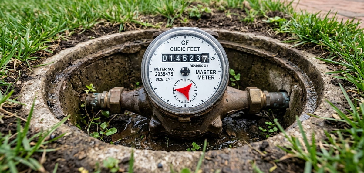
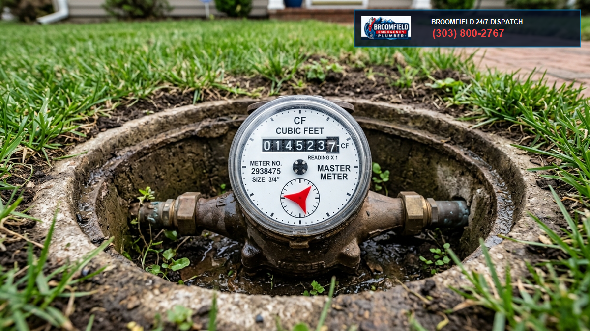
- Quarterly: Perform dynamic pressure testing at the furthest fixture stop on each floor. Verify running pressure remains above 35 PSIG under multi-fixture demand. Inspect water meter registers during closed building hours to detect unmonitored baseline leaks.
- Annually: Master plumbers must disassemble and rebuild high-traffic flushometers. Replace worn elastomeric diaphragms, vacuum breaker inserts (ASSE 1001), and handle packing O-rings. Inspect supply stops for positive mechanical lockup.
Need Emergency Commercial Flushometer Repair or Restroom Flood Restoration in Broomfield?
Is a commercial flushometer continuously dumping water in your building? Are toilets backing up, handles chattering, or is your public restroom flooded?
Call Broomfield’s commercial plumbing emergency specialists at (303) 647-3363. Our licensed master plumbers carry genuine Sloan and Zurn piston and diaphragm rebuild kits, electronic water leak detection tools, and high-velocity drain clearing equipment to secure your facility 24 hours a day, 7 days a week.