
Outside a commercial medical facility, luxury automobile dealership, or Class A corporate campus in Broomfield, Colorado, an engineered hydronic in-slab radiant snowmelt system keeps emergency access ramps, pedestrian plazas, and parking garage helices clear of winter ice. But inside the primary mechanical boiler plant, an unsettling symptom appears.
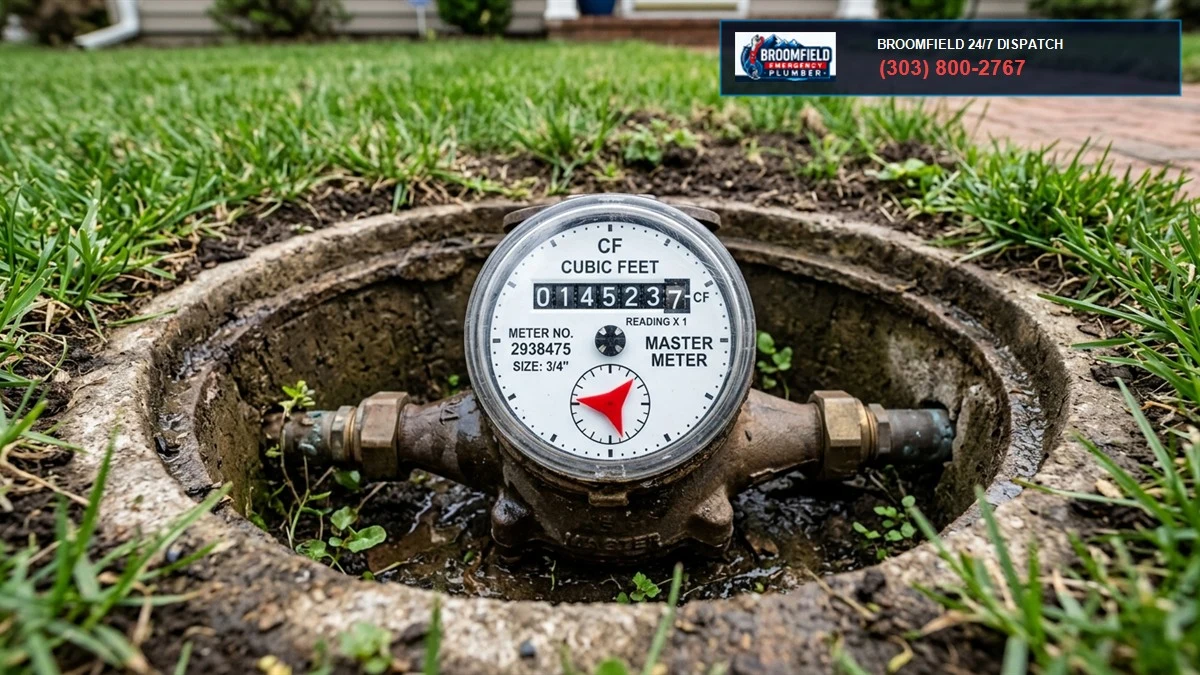
The system makeup water meter is spinning steadily.
The low-pressure hydronic loop alarm trips twice a week.
Every seven days, the closed-loop heating circuit loses **twenty-five to forty gallons of treated glycol fluid**.
Yet across twenty-five thousand square feet of finished post-tensioned concrete pavement, there is not a single puddle of standing water. No obvious steam rises from the snow.
Where is the pressurized heat-transfer fluid going?
Somewhere beneath eight inches of structural concrete and four inches of high-density extruded polystyrene insulation, an underground 3/4-inch PEX-a hydronic tube has suffered a pinhole rupture or mechanical fitting pull-out.
The escaping 130°F glycol water is quietly pooling beneath the slab, saturating the road base gravel, washing out structural subgrade, accelerating foundation settlement, and destroying the thermal efficiency of the entire commercial heating loop.
You cannot find a sub-slab hydronic leak by jackhammering random exploratory trenches across a commercial apron.
Saw-cutting post-tensioned slabs risks severing high-tension structural steel cables under thirty-five thousand pounds of tension, triggering catastrophic structural slab collapse.
Locating buried hydronic leaks demands advanced non-destructive technology: **High-Resolution Infrared Thermographic Imaging**, ultrasonic frequency acoustic listening arrays, and industrial **helium tracer gas spectrometry**.
Let’s examine the thermodynamics of in-slab radiant heating, calculate hydraulic head loss and thermal dissipation, analyze DIN 4726 oxygen barrier breakdown, review ASTM F876 PEX standards, and detail master plumber surgical non-invasive repair protocols across the Colorado Front Range.
1. The Mechanical Engineering of Commercial In-Slab Radiant Hydronic Systems
How does hot water embedded inside cold concrete melt twelve inches of heavy Colorado snow?
Commercial in-slab radiant heating operates on fundamental thermodynamic principles: conduction through solid concrete, convection into outside air, and radiant thermal exchange.
Under **ASHRAE Handbook standards and International Plumbing Code (IPC) Chapter 12 (Hydronic Piping)**, commercial snowmelt and radiant floor systems are engineered with closed-loop fluid circuits:
- High-Efficiency Condensing Boilers: Gas-fired boilers or commercial heat pumps heating heat-transfer fluid to supply temperatures between **110°F and 140°F (43°C to 60°C)**.
- Brazed Plate Heat Exchangers: Isolate boiler water from outdoor snowmelt loops to prevent glycol contamination and protect boiler heat exchangers.
- Hydronic Distribution Manifolds: Stainless steel or heavy cast brass manifolds equipped with precision balancing circuit flow meters, isolation ball valves, and digital electro-thermal zone actuators.
- Cross-Linked Polyethylene Tubing (PEX-a / PEX-b / PE-RT): Engineered 5/8-inch, 3/4-inch, or 1-inch continuous tubing embedded within the slab at 6-inch to 12-inch on-center spacing.
- Inhibited Propylene Glycol Heat-Transfer Fluid: A 40% to 50% concentration by volume of inhibited glycol and demineralized water protecting against freeze bursts down to -50°F (-45°C).
| Tubing Specification | Manufacturing Standard | Cross-Linking Method | Thermal / Chemical Vulnerability |
|---|---|---|---|
| PEX-a (Engel Method) | ASTM F876 / F877 | Peroxide Cross-Linking (> 85%) | Highest flexibility and thermal memory; vulnerable to external aggregate puncture without proper bed. |
| PEX-b (Silane Method) | ASTM F876 / F877 | Moisture-Cured Silane (65 – 70%) | Higher tensile burst strength; stiffer bend radius, prone to stress-crack notch failure when kinked. |
| PE-RT (Raised Temp) | ASTM F2623 | Non-cross-linked Copolymer | Lower cost, easily recyclable; lower long-term continuous operating temperature ceiling (140°F). |
| Synthetic EVOH Barrier | DIN 4726 Standard | Ethylene Vinyl Alcohol Copolymer | Abrasion against rough concrete aggregate destroys oxygen barrier film, triggering boiler erosion. |
When functioning properly, fluid glides through continuous buried loops without a single hidden joint beneath the concrete.
However, when aggressive Front Range soil settlement, construction stake punctures, or oxygen permeation attack the tubing, sub-slab pressure collapses.
Front Range Bentonite Clay Settlement & Grade Beam Shear
Why do commercial radiant systems in Broomfield suffer disproportionately high failure rates compared to systems installed in other states?
The answer lies in our native geology. Broomfield, Boulder County, and northern Jefferson County sit atop deep deposits of expansive smectite bentonite clay.
When bentonite clay absorbs water during wet spring snowmelts, it swells with immense hydraulic pressure—often exerting uplift pressures exceeding ten thousand pounds per square foot.
During arid summer dry spells, the clay shrinks dramatically, desiccating and pulling away from concrete footings.
This severe cyclical soil expansion and contraction exerts massive differential shear stress on commercial slabs:
- Grade Beam Transition Shear: Radiant manifolds are typically mounted inside a building mechanical room on a structural spread footing, while heating loops pass through exterior foundation walls into an outdoor slab supported on grade.
- Differential Foundation Movement: As the outdoor slab settles while the grade beam remains anchored to deep drilled piers, the embedded PEX tubing is subjected to vertical scissor-shear forces.
- IPC 305.4 Sleeving Mandate: Under **International Plumbing Code (IPC) Section 305.4**, pipes passing through foundation walls must be protected by a protective structural sleeve with an annular space sealed with flexible mastic.
- Shear Failure in Unprotected PEX: When contractors omit protective sleeves and pour concrete tight against bare tubing, differential movement slices the PEX tubing like a guillotine.
2. Thermodynamics of Slab Conduction: Fourier’s Law and Thermal Plume Diffusion
How does heat move from an embedded pipe through eight inches of concrete to the surface?
Thermal transfer through solid pavement is modeled by **Fourier’s Law of Heat Conduction**:
Where:
- $q$ = Conductive heat transfer rate ($BTU/hr$ or $Watts$)
- $k$ = Thermal conductivity of the slab composite ($k \approx 0.80 \text{ to } 1.40 \text{ BTU/(hr}\cdot\text{ft}\cdot^\circ\text{F)}$ for structural concrete)
- $A$ = Surface area of heat transfer ($ft^2$)
- $\frac{dT}{dx}$ = Temperature gradient through slab thickness ($^\circ\text{F/ft}$)
Thermal Signatures: Normal Operation vs. Active Leak
In an undamaged radiant slab, infrared thermography displays a regular, geometric pattern: distinct parallel lines of uniform temperature corresponding exactly to the engineered loop spacing (typically 9″ or 12″ centers).
When an underground tube ruptures, Fourier’s conduction model breaks down as forced convective fluid transport takes over:
- Fluid Migration into Sub-Base Gravel: Pressurized 130°F fluid sprays out of the pinhole orifice, saturating the porous aggregate sub-base beneath the slab.
- Lateral Thermal Bloom: Because fluid flows through the path of least hydraulic resistance, warm glycol water pools beneath the concrete, spreading outward in an irregular radial shape.
- Surface Thermal Signature Disruption: On the thermal camera monitor, the crisp parallel line pattern vanishes. It is replaced by an intense, blurry, amoeba-like **thermal bloom** spanning four to eight feet in diameter.
- Center of Mass Temperature Peak: The center of the bloom exhibits the highest surface radiation temperature, pinpointing the subsurface fracture epicenter within inches.
3. DIN 4726 Oxygen Barrier Breakdown & Electrochemical Heat Exchanger Erosion
Why do radiant heating tubes develop pinholes from the inside out?
The silent destroyer of closed-loop hydronics is **oxygen ingress**.
Standard polyethylene tubing is naturally permeable to atmospheric oxygen. Microscopic oxygen molecules pass directly through the solid plastic wall into the circulating water column.
To prevent this, radiant heating tubes feature a specialized microscopic outer barrier film: **Ethylene Vinyl Alcohol (EVOH)** conforming to German standard **DIN 4726**.
Under **DIN 4726**, oxygen permeability must not exceed **0.32 milligrams per square meter per day ($mg/(m^2\cdot\text{day})$)** at 104°F (40°C).
The Molecular Chemistry of EVOH Barrier Degradation
In commercial snowmelt systems, the EVOH oxygen barrier fails through two primary mechanisms:
- Pencil Vibrator Aggregate Mechanical Scuffing: When commercial concrete crews place high-strength structural mix, they insert high-frequency mechanical pencil vibrators to consolidate aggregate around post-tensioned tendons and rebar cages. When vibrating heads hit bare PEX tubes tied to wire mesh, the vibrating steel scuffs and gouges the outer EVOH skin, stripping the microscopic barrier away.
- Thermal Cycling Delamination: Extreme Colorado temperature swings (cycling between -15°F outdoor freeze shutdowns and 140°F rapid boiler firing) create severe differential thermal expansion between the cross-linked polyethylene core and the EVOH surface polymer. Over hundreds of thermal cycles, the exterior barrier blisters, cracks, and flakes off into the surrounding concrete matrix.
Once the oxygen barrier is compromised, atmospheric oxygen dissolves into the hydronic fluid at rates exceeding 5.0 mg/(m²·day).
Dissolved oxygen reacts with copper manifolds, cast iron pump volutes, and brazed plate heat exchangers:
Magnetite sludge circulates through the tubing at high velocity, acting as an internal liquid abrasive that erodes tube bends, chokes balancing valves, and burns out circulation pump seals.
PEX Manufacturing Chemistry: Engel Method vs. Silane vs. Radiation
Not all PEX tubing responds equally to sub-slab stresses. The manufacturing method dictates long-term chemical durability:
- PEX-a (Engel Method / ASTM F876): Cross-linking occurs during extrusion while the polymer is above its crystalline melting point, achieving cross-link densities exceeding 85%. PEX-a exhibits exceptional thermal memory. If a PEX-a tube kinks on site, heating it with an industrial hot-air gun restores its original cylindrical geometry without loss of burst strength.
- PEX-b (Silane Method / ASTM F876): Cross-linking occurs post-extrusion in a hot moisture sauna, reaching 65% to 70% cross-linking. PEX-b is stiffer and has higher tensile strength, but lacks thermal shape memory. A kinked PEX-b tube cannot be heated; it must be cut out and repaired with mechanical couplings.
- PEX-c (Radiation Method / ASTM F876): Cross-linking occurs via high-energy electron beam bombardment. While environmentally clean, cross-linking is often less uniform across thick pipe walls, rendering it vulnerable to micro-crack propagation under extreme thermal shock.
4. Hydraulic Friction Loss, Reynolds Numbers & Darcy-Weisbach Calculations
How does a master plumber determine which specific circuit is leaking among twenty identical loops?
Through precision **hydraulic pressure drop and flow rate analysis**.
Fluid flow resistance through embedded PEX tubing is calculated using the **Darcy-Weisbach Equation**:
Where:
- $h_f$ = Frictional head loss ($feet$ of fluid head)
- $f$ = Darcy friction factor (accounting for glycol fluid viscosity)
- $L$ = Length of the individual PEX circuit (typically 250 to 300 feet per loop)
- $D$ = Internal diameter of the tubing ($ft$)
- $v$ = Fluid velocity ($ft/s$)
- $g$ = Gravitational acceleration ($32.2 \text{ ft/s}^2$)
The Impact of Glycol Viscosity and Reynolds Number ($Re$)
Propylene glycol is substantially denser and more viscous than plain municipal tap water. Fluid viscosity shifts dramatically across temperature ranges:
Where $\rho$ is fluid density, $\mu$ is dynamic viscosity, and $\nu$ is kinematic viscosity.
Consider a standard 50/50 propylene glycol and water mixture:
- At 40°F cold start conditions, kinematic viscosity $\nu$ is approximately **10.5 centistokes ($cSt$)**. Flow is laminar or transitionally turbulent ($Re < 2,300$), resulting in high Darcy friction factors ($f > 0.035$).
- At 130°F normal operating conditions, kinematic viscosity drops to **1.8 centistokes ($cSt$)**. Flow transitions to fully developed turbulent flow ($Re > 4,000$), reducing friction factor to $f \approx 0.022$.
When circulating cold glycol through long loops, pump head demand spikes by 25% to 35% compared to plain water.
| Circuit Status | Measured Flow Rate (GPM at 8 PSI Head) | Dynamic Pressure Loss ($\Delta P$) | Diagnostic Interpretation |
|---|---|---|---|
| Loop 1 (Normal / Balanced) | 1.4 GPM | 7.8 PSI | Proper circuit flow; zero leakage. |
| Loop 2 (Normal / Balanced) | 1.4 GPM | 7.9 PSI | Proper circuit flow; zero leakage. |
| Loop 3 (Partially Obstructed) | 0.6 GPM | 12.4 PSI | Scale accumulation or kinked tubing in concrete. |
| Loop 4 (ACTIVE RUPTURE) | 2.8 GPM (Abnormally High) | 3.2 PSI (Abnormally Low) | Fluid discharging directly into sub-slab void; ZERO backpressure. |
Look closely at Loop 4 in the diagnostic data table above.
When an underground pipe ruptures, the fluid no longer has to travel through 300 feet of restrictive tubing to return to the manifold. It discharges directly into the soil at the 80-foot mark.
Frictional resistance collapses, causing flow rate to surge while circuit backpressure plummets.
Modern ECM (electronically commutated motor) circulator pumps, such as Grundfos Magna3 or Taco 0034e pumps, adjust their variable speed curves to maintain constant differential head.
When a radiant loop ruptures, the ECM pump ramps up to maximum RPM, hunting for head pressure that never materializes. This constant high-speed hunting provides an unmistakable digital alert in the mechanical room.
By inspecting manifold sight glass flow meters under dynamic pump pressure, our master plumbers isolate the damaged loop within sixty seconds without touching a single diagnostic tool to the pavement.
5. Non-Destructive Diagnostic Workflow: Infrared, Acoustics & Helium Tracer Gas
Once the manifold identifies the leaking circuit, how do you locate the exact pinhole beneath eight inches of post-tensioned concrete?
Our master plumbers execute a structured **3-Phase Non-Invasive Diagnostic Protocol**:
Phase 1: High-Resolution Thermal Imaging Survey
- We isolate the compromised loop and purge it of air using our mobile high-volume flushing cart.
- We inject high-temperature water (140°F) under controlled pressure into that specific circuit while all other circuits remain unheated.
- A master technician walks the pavement with a FLIR high-thermal-sensitivity infrared camera (thermal sensitivity < 0.03°C).
- The thermal camera detects the subsurface thermal plume emerging through the concrete, narrowing the leak location down to a four-foot zone.
Phase 2: Ultrasonic Acoustic Ground Microphone Triangulation & Cross-Correlation
- Thermal conduction through thick concrete can diffuse outward, creating a broad surface plume. To pinpoint the exact fracture epicenter, we switch to acoustic mechanics.
- We pressurize the loop to 60 PSI with dry nitrogen gas. Escaping gas and water create high-frequency acoustic friction vibrations (1,000 Hz to 3,000 Hz).
- We deploy piezoelectric ground microphone sensors with heavy acoustic shields across the thermal plume area.
- When manifolds allow dual-sensor access, we run a digital leak noise correlator calculating time delay $\Delta t$ between acoustic arrival points:
Where $L$ is total loop distance between sensor pickups, $c$ is the acoustic wave propagation velocity through fluid-filled polymer pipe ($c \approx 450 \text{ to } 650 \text{ m/s}$ in buried PEX), and $d_1$ is the physical distance from sensor 1 to the pipe rupture.
The digital acoustic analyzer records decibel levels down to 0.1 dB resolution. The highest acoustic decibel peak marks the physical breach down to a six-inch circle.
Phase 3: Molecular Helium Spectrometry (For Deep or Insulated Slabs)
- If the concrete slab sits on thick foam insulation or deep structural void forms that dampen acoustic waves, we inject a 95/5 nitrogen-helium tracer blend into the dry pipe.
- Helium effuses through the microscopic plastic fracture and migrates vertically through the concrete slab 2.7 times faster than air.
- Our mass spectrometer sniffer sweeps the surface, detecting helium emergence down to 1 PPM to confirm the exact drilling coordinate.
6. Post-Tensioned (PT) Slabs: The Extreme Hazard of Blind Cutting
Why is blind saw-cutting strictly prohibited on modern commercial concrete slabs in Broomfield?
Most commercial parking structures, office foundations, and luxury ramps are built using **Post-Tensioned (PT) Concrete**.
Inside the concrete slab lie hundreds of high-strength unbonded seven-wire steel tendons encased in plastic sheathing.
During construction, after the concrete cures, hydraulic jacks pull these tendons to tensile loads exceeding **33,000 to 35,000 pounds per tendon**.
What Happens When a Tendon is Cut
If an inexperienced contractor cuts into a post-tensioned slab with a concrete saw and strikes a tensioned cable:
- The cable snaps instantly with the explosive kinetic force of an artillery shell.
- The severed tendon shoots out through the exterior edge of the building or punches upward through the concrete slab, easily penetrating structural walls, machinery, or human workers.
- The structural integrity of the entire building bay is permanently compromised, requiring emergency structural shoring costing hundreds of thousands of dollars.
Our master plumbers **NEVER penetrate a commercial slab without Ground Penetrating Radar (GPR) Scanning**.
Our GPR systems scan up to 24 inches deep, mapping the exact layout of all post-tensioned cables, rebar mats, and electrical conduits.
We mark a safe clearance corridor before drilling, ensuring zero risk to building structural integrity.
7. Surgical Sub-Slab Repair: Core Drilling, PPSU Fittings & ASTM F2080 Compression Sleeves
Once the leak is pinpointed and structural cables are mapped, how is the buried PEX tube permanently repaired?
We execute a **Surgical Core-Drill Restoration**:
- Precision Diamond Core Drilling: Rather than jackhammering a huge crater, we use a water-cooled diamond core drill to extract a neat 6-inch or 8-inch cylindrical concrete core directly above the leak point.
- Careful Hand Excavation: We gently hand-vacuum the loose aggregate and foam insulation around the ruptured PEX tube, exposing 12 inches of pipe without scratching adjacent loops.
- Excision of Damaged Section: We cut away the split pipe segment using calibrated PEX cutters.
- Installation of Engineered Mechanical Fittings: We never use cheap push-fit or standard crimp rings beneath concrete. Codes mandate high-integrity permanent fittings:
- ASTM F2080 Cold-Expansion Compression-Sleeve Fittings: A solid brass or PPSU (polyphenylsulfone) fitting inserted into the flared PEX tube, locked permanently with a heavy brass compression sleeve pressed under 10,000 PSI hydraulic force.
- ASTM F1960 ProPEX Expansion Rings: Thermal memory PEX rings expanded over cold-expansion fittings, creating an indestructible monolithic connection.
- Triple-Layer Corrosion Protection: The completed brass fitting is encased in self-vulcanizing silicone tape, wrapped in petrolatum tape, and enclosed in an elastomeric split boot to isolate metal from corrosive Portland cement.
- Hydrostatic Proof Testing: The repaired loop is pressurized to **100 PSI with clean water for 2 hours**, verifying zero gauge pressure decay.
- Structural Re-Grouting: The core hole is backfilled with non-shrink structural hydraulic epoxy grout (minimum 8,000 PSI compressive strength), restoring original slab load-bearing capacity.
8. Case Studies from Broomfield: Commercial Snowmelt Restorations
Real-world commercial radiant repairs demonstrate the power of non-invasive precision:
Case Study 1: The Emergency Room Ambulance Ramp Save in Broomfield
The Building: A regional medical center emergency department in Broomfield.
The Crisis: In mid-December, the primary ambulance arrival ramp snowmelt system suffered a sudden low-pressure trip. Boilers locked out, leaving the steep 12% grade ramp covered in hazardous black ice. Shutting down the ambulance entrance for structural excavation would force emergency reroutes for four weeks.
Our Master Plumber Diagnosis: We isolated the twelve snowmelt circuits at the mechanical manifold. Manifold flow meters showed Circuit 7 drawing 3.4 GPM with near-zero backpressure. We fired Circuit 7 with 135°F water and swept the ramp with our FLIR thermal imaging camera. Within 20 minutes, a distinct thermal bloom was detected 18 feet up the ramp. We confirmed the coordinate using our ultrasonic ground microphone, pinpointing the leak to a 4-inch target.
The Restoration: GPR scanning verified a 3-inch clear window between two post-tensioned cables. We core-drilled an 8-inch hole, excavated six inches of gravel, and uncovered a 3/4″ PEX-a tube that had rubbed against a sharp rebar chair tie until a pinhole developed. We installed an ASTM F2080 brass compression sleeve, hydrostatically tested the repair at 100 PSI, and poured rapid-setting 8,000 PSI structural grout. The entire repair took 5.5 hours. Ambulances were rolling safely over the heated ramp that evening.
Case Study 2: Auto Dealership Heated Customer Plaza in Flatiron
The Building: A premier luxury automobile dealership featuring a 15,000-square-foot heated stamped-concrete display apron.
The Crisis: The dealership was losing 30 gallons of glycol fluid weekly, accompanied by a chemical vinegar smell near the service drive. Management feared the entire $220,000 stamped decorative concrete slab would have to be torn out.
Our Master Plumber Diagnosis: Infrared thermography identified an abnormal thermal bloom directly adjacent to a newly installed flag pole footer. An uninspected sub-contractor had driven a steel ground anchor through the decorative slab eight months prior, grazing an embedded 5/8″ hydronic line.
The Restoration: We core-drilled a clean 6-inch decorative plug, repaired the perforated PEX-a line using an ASTM F1960 ProPEX fitting, matched the stamped concrete color matrix, and restored the apron seamlessly. The repair is completely invisible to dealership customers.
Case Study 3: Luxury Hotel Valet Circle in Interlocken Broomfield
The Building: A four-star corporate hotel in Interlocken featuring an upscale heated granite paver porte-cochere with twenty-four radiant loops.
The Crisis: The hotel snowmelt loop lost dynamic operating pressure every forty-eight hours, causing the makeup system to introduce unconditioned municipal water. Boiler safety interlocks triggered low-water cutoffs, leaving the valet drive slick with freezing slush. Management received quotes from commercial excavators proposing to demolish eighty linear feet of imported granite pavers, projecting \$140,000 in structural restoration costs.
Our Master Plumber Diagnosis: Our emergency hydronic team isolated the twenty-four manifold circuits. Static nitrogen testing at 80 PSI revealed Circuit 19 dropped 40 PSI in under ninety seconds. Injecting 140°F fluid into Loop 19 produced an unmistakable subsurface thermal signature directly below the transition curb where the slab met the foundation grade beam. Expansive clay subsoil heave had settled the apron slab three-quarters of an inch, shearing the un-sleeved PEX riser against the foundation foot.
The Restoration: We deployed ground penetrating radar to pinpoint nearby high-voltage conduit, carefully lifted exactly two granite paver units by hand, core-drilled a 6-inch access opening through the concrete substrate, and fitted an ASTM F2080 compression-sleeve coupling with engineered elastomeric flex joints to accommodate future foundation movement. After a flawless 100 PSI hydrostatic pressure proof test, we grouted the core and reset the original pavers. Total project downtime was under eight hours, saving the hotel over \$130,000 in demolition and reconstruction expenses.
9. Glycol Chemistry & Fluid Restoration: Testing pH, Reserve Alkalinity & Freeze Protection
Whenever a radiant snowmelt system leaks, fresh municipal water is added to maintain pressure.
Diluting glycol with tap water initiates a dangerous chemical chain reaction:
| Chemical Metric | Healthy Closed Loop Standard | Diluted / Degraded Metric | Consequence to Hydronic System |
|---|---|---|---|
| Propylene Glycol Concentration | 40% to 50% by Volume | < 30% (Diluted by tap water) | Freeze point rises from -28°F to +15°F; ice burst hazard. |
| Fluid pH | 8.5 to 10.0 (Alkaline buffer) | < 7.0 (Acidic breakdown) | Aggressive organic acids dissolve brass, copper, and cast iron. |
| Reserve Alkalinity (RA) | > 10.0 mL of 0.1N HCl | < 3.0 mL | Fluid loses ability to neutralize combustion and thermal acids. |
| Specific Conductance | < 1,500 $\mu S/cm$ | > 4,000 $\mu S/cm$ | High dissolved metals accelerate galvanic electrolytic corrosion. |
The Chemical Oxidation Chain of Degraded Glycol
When heated glycol mixes with fresh dissolved oxygen introduced via makeup water, thermal-oxidative degradation accelerates exponentially:
These aggressive carboxylic acids strip copper from boiler heat exchangers, deposit black copper sulfide scales inside tubing, and pit stainless steel manifold bodies.
Following any leak repair, our master plumbers test circulating fluid using digital refractometers and calibrated laboratory pH meters.
If fluid pH has dropped below 7.5 or reserve alkalinity is depleted, we dump the degraded solution, flush the system with chemical neutralizing agents, and recharge the loop with virgin inhibited propylene glycol blended with demineralized reverse-osmosis water.
Our fluid recharge packages feature specialized multi-metal corrosion inhibitors, including tolyltriazole to passivate yellow metals (copper and brass) and borate-molybdate buffers to protect cast iron circulator volutes and steel piping headers.
10. Seasonal Preventive Maintenance Checklist for Commercial Snowmelt Systems
Guarantee reliable winter operation across your commercial hydronic heating assets with this annual protocol:
| Frequency | Maintenance / Inspection Action | Target Value / Benchmark | Corrective Action if Non-Compliant |
|---|---|---|---|
| Monthly (Winter Season) | Check hydronic loop expansion tank pressure | 15 to 25 PSI static cold pressure | Recharge bladder with dry nitrogen; inspect for leaks if pressure drops. |
| Monthly (Winter Season) | Monitor automated makeup water meter | Zero gallons consumption | Any makeup water consumption indicates an active underground leak. |
| Biannually (Autumn & Spring) | Laboratory test glycol pH and freeze point | pH > 8.5; Burst point < -40°F | Add inhibitor buffer package or recharge with fresh 50/50 glycol mix. |
| Annually (Pre-Winter / October) | Cycle and test all manifold balancing valves | Flow sight glasses move freely | Clean sight glass flow meters; replace sticky electro-thermal actuators. |
| Annually (Pre-Winter) | Infrared thermal survey during pre-season test firing | Uniform parallel thermal stripes | Isolate and repair any circuits showing thermal bloom anomalies. |
| Annually (Pre-Winter) | ECM pump operational vibration & delta-T review | Temperature differential 20°F – 30°F | Check impellers for magnetite scale buildup; balance return circuit throttling. |
11. Emergency Action Steps: What to Do When Your Radiant Snowmelt System Leaks Right Now
If your commercial radiant heating system is losing pressure or alarms are sounding:
- Shut Off the Automatic Makeup Water Feeder: Immediately close the manual bypass valve on the water makeup line. Allowing tap water to feed the system continuously dilutes expensive glycol, promotes aggressive oxygen corrosion, and masks active sub-slab leaks.
- Inspect the Primary Mechanical Room: Check expansion tanks, boiler relief valves, and circulation pump flanges for visible standing water before assuming the leak is underground.
- Record Manifold Flow Meter Readings: Photograph the sight-glass flow meters on the supply and return manifolds under dynamic pump operation to identify circuits with abnormal flow or pressure loss.
- Do NOT Allow Saw-Cutting of Concrete: Prohibit general maintenance workers or paving contractors from saw-cutting the slab until post-tensioned cables and PEX loops are mapped with ground-penetrating radar.
- Call Licensed Commercial Master Plumbers Immediately: Contact our rapid-response commercial hydronics dispatch at (303) 647-3363. We deploy FLIR thermal imaging cameras, ultrasonic listening gear, helium tracer rigs, GPR radar, and certified radiant technicians 24/7 across Broomfield and the Denver Metro area.
Frequently Asked Questions (FAQ)
How do you find a water leak under concrete without digging up the whole floor?
We use non-destructive diagnostic physics: high-resolution infrared thermal imaging to trace the heat bloom of escaping 130°F fluid, ultrasonic ground microphones to pinpoint acoustic escaping fluid vibrations, and industrial helium tracer gas spectrometry to detect molecular gas emergence through the concrete. This pinpoints the leak down to a six-inch target area.
Why is saw-cutting post-tensioned concrete dangerous for radiant repairs?
Post-tensioned concrete slabs contain high-strength steel tendons tensioned to over 33,000 pounds of force. Cutting a tendon with a concrete saw causes the cable to snap violently like an explosive projectile, compromising building structural integrity and creating severe life-safety hazards. Ground Penetrating Radar (GPR) scanning is mandatory before any concrete penetration.
What type of fitting is code-approved for repairing buried PEX tubing under a concrete slab?
Under International Plumbing Code (IPC) Chapter 12 and ASTM standards, buried sub-slab repairs require permanent, high-integrity mechanical fittings—specifically ASTM F2080 cold-expansion compression-sleeve fittings or ASTM F1960 ProPEX expansion rings. Push-fit or crimp-ring fittings are prohibited beneath structural concrete.
Why does glycol fluid turn dark and acidic in a radiant snowmelt system?
Glycol fluid degrades when oxygen permeates through compromised tubing barriers (or through repeated additions of fresh tap water). Oxygen oxidizes the glycol into aggressive organic acids (glycolic, formic, and oxalic acids), dropping fluid pH below 7.0 and causing severe corrosion of brass manifolds, copper piping, and heat exchangers.
How long does a surgical core-drill radiant slab repair take?
A surgical non-invasive core-drill repair is typically completed within 4 to 6 hours from arrival. This includes thermal and acoustic pinpointing, GPR cable scanning, diamond core drilling, installing certified ASTM compression fittings, hydrostatic testing at 100 PSI, and pouring structural hydraulic non-shrink grout.
Commercial Radiant Snowmelt Leak in Broomfield?
Don’t let a sub-slab hydronic leak destroy your heating boilers, freeze your ramps, or ruin concrete assets. Our licensed master plumbers use infrared thermal imaging, ultrasonic acoustics, and surgical core-drill repairs to fix leaks with zero guesswork.