
You walk down the stairwell into the sub-grade mechanical vault of an eight-story Broomfield commercial office tower or luxury apartment complex. Before you even unlock the door, a high-frequency gravel-churning roar vibrates through the concrete foundation. Inside, water is spraying in an atomized mist from the motor lantern bracket of Lead Pump 1 on the triplex booster skid. A steady, scalding trickle of water is pooling around the inertia base, overflowing the floor drain trench and threatening the variable frequency drive (VFD) electronics cabinets.
Your domestic water booster pump is tearing itself apart.
Upper floor tenants are already blowing up the facility management phone line. Penthouse water pressure has plummeted from seventy-five pounds per square inch (PSI) down to a sluggish trickle.
What happened?
The mechanical seal cartridge suffered catastrophic face fracture, while the pump volute is enduring destructive suction cavitation. Along the Colorado Front Range, our 5,400-foot altitude slashes available atmospheric barometric pressure, making high-rise booster systems exceptionally vulnerable to Net Positive Suction Head Available ($NPSH_a$) collapse.
When water boils into vapor bubbles at room temperature inside your pump suction eye and those bubbles collapse against precision stainless steel impellers, the impact pressure reaches 100,000 PSI. It chews metal away like termitic acid.
Let’s examine the hydraulic physics of commercial booster pumps, calculate high-altitude NPSH thresholds, troubleshoot silicon-carbide mechanical seal degradation, and explore master plumber emergency repair protocols.

1. Anatomy of a Commercial Booster Skid: Triplex Staging & VFD Modulation
Why can’t municipal water mains supply a multi-story commercial building directly?
Municipal water utilities typically deliver potable water to the property curb stop at 45 to 65 PSI.
Water is heavy. For every vertical foot of pipe rise, gravity exerts a downward hydrostatic head pressure of 0.433 PSI (or 1 PSI for every 2.31 feet of vertical elevation).
In an eight-story building standing 90 feet tall with backflow preventers, pressure reducing valves, water softeners, and fixture pipe friction:
Subtract that 39 PSI elevation penalty, plus 12 PSI through the reduced pressure zone (RPZ) backflow assembly, plus 15 PSI piping friction loss, from a 50 PSI street main.
Result: -16 PSI.
The top four floors wouldn’t get a single drop of water.
To overcome this gravity deficit, commercial facilities install packaged triplex vertical multi-stage centrifugal booster skids (such as Grundfos CR, Bell & Gossett e-SV, or Armstrong Design Envelope). Three pumps sit on a common structural steel header, modulated by individual variable frequency drives (VFDs) that adjust pump motor RPM in milliseconds to maintain a rock-solid discharge setpoint (e.g., 85 PSI) regardless of how many flush valves open simultaneously.
2. Mechanical Seal Mechanics: Silicon Carbide, Tungsten & Carbon Faces
Where the pump shaft exits the pressurized water chamber to connect to the electric motor, a mechanical seal must hold back 150+ PSI of water while spinning at 3,500 RPM.
Traditional packing rope is obsolete in modern commercial plumbing. Modern skids rely on cartridge mechanical seals consisting of two micro-lapped mating faces:
- The Stationary Face: Fixed solidly inside the pump head gland plate.
- The Rotating Face: Locked to the spinning stainless steel shaft via drive collars and compressed by precision wave springs.
The Microscopic Fluid Film
Here is the engineering marvel: the two seal faces do not touch directly during normal operation.
A microscopic hydrodynamic fluid film—roughly **1 micrometer (0.00004 inches) thick**—separates the rotating face from the stationary face. This microscopic boundary layer of pumped water lubricates the faces and carries away friction heat.
| Seal Face Material Pairing | Hardness (Mohs / Knoop) | Thermal Shock Resistance | Dry-Run Tolerance | Best Commercial Application |
|---|---|---|---|---|
| Carbon Graphite vs. Silicon Carbide (SiC) | Carbon: Medium SiC: 9.5 Mohs (Extremely Hard) |
High | Moderate (Self-lubricating carbon provides brief margin) | Clean domestic potable water systems with low mineral scale. |
| Silicon Carbide vs. Silicon Carbide (SiC/SiC) | Extremely Hard (2,500 Knoop) | High | Near Zero (Fails within 30 seconds of dry run) | Abrasive Front Range hard water, sand/sediment resistance. |
| Tungsten Carbide vs. Tungsten Carbide (TC/TC) | Maximum Fracture Toughness | Exceptional | Very Low | Heavy industrial, high-pressure booster stages (> 250 PSI). |
Why Seals Explode: Thermal Shock & Dry Running
What kills a silicon carbide mechanical seal?
Dry running.
If the municipal water supply drops pressure or an upstream valve is throttled during maintenance, the booster pump can be starved of water. Without that 1-micrometer water film, the rotating and stationary faces rub dry under heavy spring load.
Within twenty seconds, friction drives localized face temperatures above 800°F.
Then, municipal water rushes back into the pump volute. Cold 50°F water hits 800°F silicon carbide.
Thermal shock fracture occurs instantly. The brittle silicon carbide face shatters like crystal glass. High-pressure water blasts through the seal chamber, pouring out of the motor lantern into the mechanical room.
3. High-Altitude Cavitation: The Physics of Front Range Suction Flashing
Why does pump cavitation occur so easily in Broomfield?
Cavitation is not water hammer. It is the formation and violent implosion of vapor bubbles inside flowing liquid.
At sea level, water boils at 212°F under 14.7 PSI atmospheric pressure. But boiling is strictly a function of temperature and local absolute pressure. If you reduce the local pressure low enough, water will boil at room temperature (65°F).
The Net Positive Suction Head Equation
For a booster pump to operate without cavitation, the Net Positive Suction Head Available ($NPSH_a$) at the pump suction flange must exceed the pump manufacturer’s Net Positive Suction Head Required ($NPSH_r$):
We calculate $NPSH_a$ using the engineering formula:
Where:
- $h_{atm}$ = Atmospheric barometric pressure head (ft of absolute water)
- $h_s$ = Static suction pressure head at the pump inlet (ft)
- $h_f$ = Friction head losses through suction piping, strainer, and backflow preventer (ft)
- $h_{vp}$ = Vapor pressure head of the water at operating temperature (ft)
The 5,400-Foot Elevation Penalty
Here is why Front Range engineering matters:
- Sea Level Atmospheric Head ($h_{atm}$): $14.7\text{ PSI} \times 2.31 = 33.95\text{ ft of water}$
- Broomfield Atmospheric Head ($h_{atm}$ at 5,400 ft): $12.2\text{ PSI} \times 2.31 = 28.18\text{ ft of water}$
You lose nearly 6 feet of absolute suction head simply by standing in Broomfield.
When morning water demand surges and water velocity through an undersized suction header climbs to 10 feet per second, friction losses ($h_f$) spike. If static city pressure droops simultaneously, local absolute pressure at the suction impeller eye plunges below the water’s vapor pressure ($h_{vp}$).
Vapor pockets erupt in the water stream.
A microsecond later, those vapor bubbles travel into the higher-pressure region of the impeller vanes. They implode violently. Micro-jets of water shoot inward at velocities exceeding 1,000 meters per second, blasting microscopic pits into the 316 stainless steel impellers and vibrating the pump shaft violently.
That vibration rapidly destroys the mechanical seal faces.
4. VFD Hunting & Harmonic Destabilization
What makes a booster pump sound like it’s surging or revving up and down uncontrollably?
Modern booster systems rely on PID (Proportional-Integral-Derivative) control loops programmed into the variable frequency drives. A 4-20 milliamp pressure transducer on the discharge header measures real-time PSI and feeds data back to the VFD processor.
When PID parameters are improperly tuned or when an expansion tank loses its nitrogen pre-charge:
- A single commercial toilet flushes on floor 4. Discharge pressure drops by 2 PSI.
- The VFD over-reacts (excessive Proportional Gain $K_p$), instantly ramping the motor from 30 Hz to 60 Hz.
- Discharge pressure overshoots to 95 PSI.
- The VFD slams on the electronic brakes, dropping motor frequency to 20 Hz.
- Pressure collapses to 65 PSI. The cycle repeats every 4 seconds.
This phenomenon is known as VFD hunting.
Continuous acceleration and deceleration twists the pump shaft with severe torsional shock loads. Within months, mechanical seal springs fatigue, coupling inserts shear, and motor bearings develop electrical fluting from high-frequency shaft currents.
5. Shaft Voltage & Electrical Bearing Fluting
Few facility managers realize that the variable frequency drive controlling their booster pump can destroy mechanical seals from the inside out.
Modern VFDs use pulse-width modulation (PWM) with insulated-gate bipolar transistors (IGBTs) switching at carrier frequencies up to 16 kHz. This ultra-fast switching induces a parasitic capacitive voltage across the motor shaft.
When this common-mode shaft voltage exceeds the dielectric breakdown threshold of the motor bearing lubricant (typically 15 to 30 volts peak):
- An electrical discharge machining (EDM) spark arcs across the steel bearing balls.
- The microscopic electrical arc melts pits into the bearing raceway, creating washboard ridges known as bearing fluting.
- As bearing tolerances loosen, radial shaft runout increases from 0.001″ to over 0.006″.
- This radial wobble causes the mechanical seal faces to wobble axially at 3,500 RPM, allowing high-pressure water to squirt past the faces with every rotation.
Master plumbers prevent EDM destruction by installing circumferential micro-fiber shaft grounding rings (such as AEGIS SGR) on all inverter-duty booster motors.
6. Master Plumber Field Diagnostics: Step-by-Step Testing Protocol
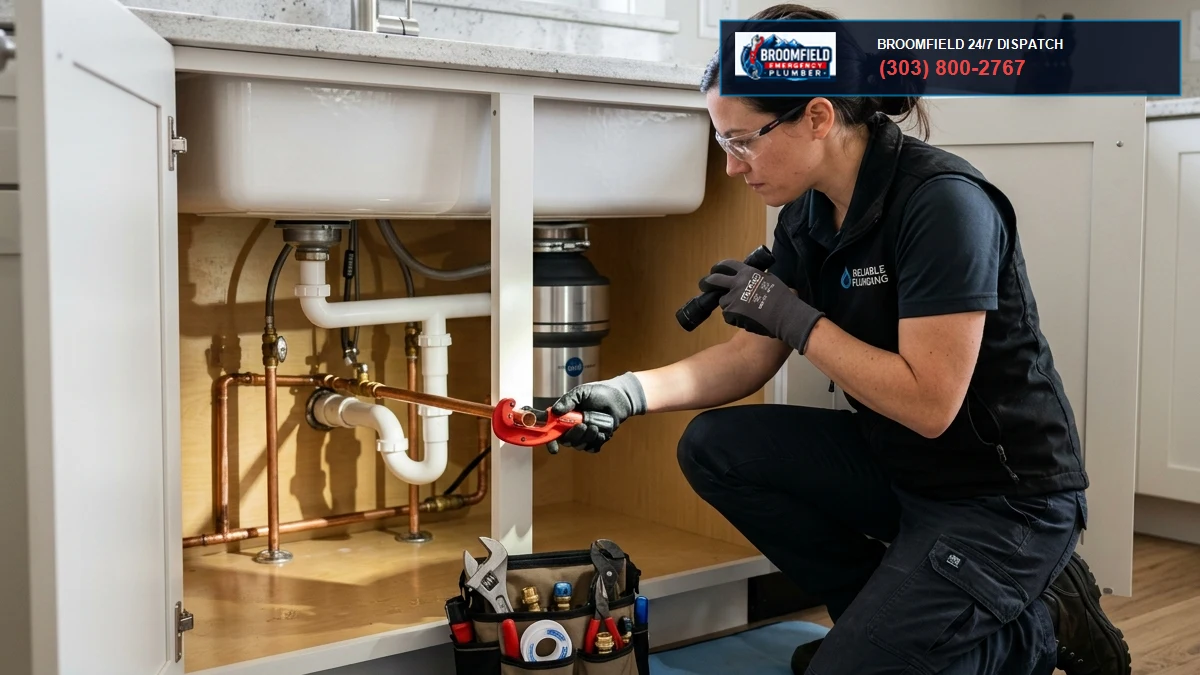
When our commercial emergency technicians arrive at a failing booster skid in Broomfield, we systematically isolate and test every hydraulic parameter:
| Diagnostic Step | Instrument / Inspection Tool | Design Benchmark | Failure Symptom & Action Plan |
|---|---|---|---|
| 1. Suction & Discharge Differential | Calibrated Liquid-Filled Gauges | Suction ≥ 25 PSI; Discharge = 75 to 90 PSI steady |
Suction gauge fluttering violently between 5 and 20 PSI confirms severe suction cavitation. Clean suction Y-strainer screen immediately. |
| 2. Acoustic Ultrasonic Vibration | Ultrasonic Stethoscope / FFT Vibration Analyzer | Smooth laminar hum (< 2.5 mm/s RMS vibration velocity) | Loud crackling noise like popping bubble wrap confirms cavitation. Check NPSHa calculation and throttle discharge valve to move pump back on curve. |
| 3. Cartridge Seal Weep Rate | Visual Inspection of Lantern Drain Port | ≤ 3 drops per hour (normal vapor lubrication) | Steady stream or spraying mist confirms face fracture or O-ring blowout. Pull motor and install new pre-assembled cartridge seal kit. |
| 4. Expansion Tank Pre-Charge | Digital Tire Pressure Gauge on Schrader Valve | Pre-charge = Cut-in Setpoint minus 5 to 10 PSI | Water spraying from air valve confirms ruptured butyl bladder. Replace tank; lack of hydraulic cushioning causes rapid VFD hunting. |
| 5. VFD Ramp Time & PID Settings | Drive Programming Interface | Ramp-up: 3.0 to 5.0 sec; Ramp-down: 4.0 to 6.0 sec |
Ultra-fast 0.5-second ramp times cause water hammer and shaft torsion. Smooth acceleration curves to protect mechanical couplings. |
7. How to Replace a Cartridge Mechanical Seal in the Field
Replacing a multi-stage pump seal no longer requires tearing down the entire 12-stage impeller stack. Master plumbers follow a precise cartridge replacement protocol:
- Isolate and De-pressurize: Close suction and discharge butterfly isolation valves. Lockout/tagout the 480V circuit breaker. Open the casing drain plug to vent all hydrostatic pressure.
- Remove Motor Coupling: Unbolt the two-piece aluminum or cast iron shaft coupling guards. Remove the axial coupling bolts. Note the exact shaft height position using a digital vernier caliper.
- Loosen Shaft Set Screws: Loosen the radial set screws locking the seal sleeve to the pump shaft.
- Extract Cartridge Gland: Unbolt the four gland bolts holding the seal plate to the pump head. Slide the old cartridge seal assembly upward off the shaft.
- Inspect Shaft Surface: Clean the stainless steel shaft with Scotch-Brite. Check for fretting, scoring, or runout. Shaft runout must measure under **0.002 inches TIR (Total Indicator Reading)** on a dial indicator.
- Install New Seal & Engage Locking Tabs: Slide the new pre-assembled cartridge seal down over the shaft, torque gland bolts to factory specs, tighten shaft set screws, and pull the plastic centering/locking clips before rotating the shaft by hand.
8. Hydraulic Pipe Sizing: Suction Header Reynolds Numbers & Turbulence
Why do booster pumps cavitate even when city pressure reads 40 PSI at rest?
The secret lies in the velocity and turbulence inside the suction manifold.
Under the Hydraulic Institute Standards (ANSI/HI 9.6.6), fluid velocity entering a multi-stage centrifugal pump suction header must not exceed 4.0 to 5.0 feet per second.
Crucially, a straight run of pipe equal to at least **five pipe diameters ($5D$)** must be provided between any elbow, reducer, or butterfly valve and the pump suction flange.
When contractors crowd a mechanical room and place an eccentric reducer or 90-degree elbow directly on the pump suction flange:
- The flow separates along the outer elbow radius.
- A localized vortex forms inside the suction eye.
- The Reynolds number ($Re = \frac{\rho v D}{\mu}$) spikes into severe turbulence ($Re > 100,000$).
- The uneven velocity distribution starves one side of the first-stage impeller, inducing asymmetric cavitation and rapid mechanical seal failure.
9. Real-World Case Study: 10-Story Broomfield Residential Tower Rescue
In December 2025, our master plumbing emergency dispatch received a priority call from a 120-unit luxury residential high-rise in Broomfield. Tenants on floors 8 through 10 had zero water pressure during the 7:00 AM morning shower rush, while the basement mechanical room had three inches of standing water.
Here is what our forensic inspection uncovered:
- The Failure: Lead Pump 1 had blown its silicon carbide seal cartridge. Water was spraying at 90 PSI directly onto the VFD panel heatsinks. Pump 2 was locked out on inverter overcurrent. Pump 3 was vibrating violently with a roaring gravel sound.
- The Root Cause: The building’s 120-gallon ASME expansion tank had blown its internal butyl bladder, completely waterlogging the tank. Without an air cushion, the VFD PID loop was hunting every 2 seconds, cycling the pumps between 15 Hz and 60 Hz hundreds of times an hour. The pressure surges fractured the brittle silicon carbide seal faces.
- The Repair: We isolated the skid, installed an emergency Grundfos cartridge seal kit, replaced the waterlogged expansion tank with an ASME-certified 150 PSI pre-charged bladder tank, recalibrated the VFD PID loop integral gain, and restored full 85 PSI domestic water pressure to the penthouse within four hours.
10. Expansion Tank Pre-Charge Calculation & Sizing Equations
A booster skid cannot function stably without a properly sized hydropneumatic expansion tank.
To determine required acceptance volume ($V_1$) for a commercial booster package:
Where pressures are expressed in PSIG and 12.2 represents absolute atmospheric pressure head at Broomfield’s 5,400-foot elevation.
Crucial Rule of Pre-Charge: The nitrogen bladder pre-charge pressure must always be calibrated with the water side hydrostatically drained to 0 PSI. Setting the pre-charge while line water pressure is applied results in false readings and rapid bladder rupture.
11. Preventive Maintenance Checklist: Keeping High-Rise Water Flowing
To prevent a sudden loss of building domestic water pressure, implement this maintenance schedule:
- Monthly Strainer Blowdown: Open the blowdown ball valve on the primary suction Y-strainer for 15 seconds under flow to clear accumulated rust flakes and municipal pipe scale.
- Quarterly Lead/Lag Rotation Audit: Verify through the digital controller that the lead pump alternates automatically every 24 operating hours to distribute mechanical seal runtime evenly across all three pumps.
- Semi-Annual Expansion Tank Bladder Inspection: Check air pre-charge pressure with the pump skid isolated and hydrostatically drained. Maintain nitrogen charge within 5 PSI of target.
- Annual Infrared Thermography: Scan pump motor bearings, shaft couplings, and drive contactor terminals for abnormal thermal rise indicating bearing failure or shaft misalignment.
- Annual Vibration FFT Analysis: Measure radial and axial vibration velocities across all bearing housings to detect early-stage impeller cavitation erosion before seal blowouts occur.
12. The Pump Affinity Laws: Energy & Hydraulic Calculations under VFD Control
How does reducing motor frequency save energy while altering booster pump head?
Variable frequency drives manipulate motor synchronous speed ($N$) by altering line AC frequency ($f$). The physical behavior of a vertical multi-stage centrifugal pump obeys the fundamental Pump Affinity Laws:
$$\text{Head Pressure: } \frac{H_1}{H_2} = \left(\frac{N_1}{N_2}\right)^2$$
$$\text{Brake Horsepower: } \frac{BHP_1}{BHP_2} = \left(\frac{N_1}{N_2}\right)^3$$
Notice the exponential cubic relationship for motor power ($BHP$). If a booster pump motor slows from 60 Hz down to 50 Hz (an approximate 17% reduction in speed):
Power consumption plummets by 42%.
However, look closely at the second affinity equation: pump head collapses by the square of speed ($\Delta H \propto N^2$). If the drive slows down too much, the pump reaches its zero-flow cutoff head.
The spinning impellers can no longer generate enough hydraulic lift to overcome static building elevation. The pump dead-heads inside its own casing, churning trapped water into boiling steam in under six minutes. To prevent this, master plumbers program a hard minimum speed cutoff (typically 25 to 30 Hz) into the VFD firmware, automatically placing the pump into sleep mode whenever demand ceases.
13. ASME Section IV Pressure Relief Valve Sizing on Booster Headers
What protects the commercial domestic water piping from bursting if the VFD processor locks up at 60 Hz?
Under the International Plumbing Code (IPC Section 604.8) and ASME Section IV standards, every commercial booster package must incorporate an independent, pilot-operated or spring-loaded high-pressure relief valve piped directly to a floor sink or mechanical room drain.
If a shorted VFD transistor drives the lead pump to maximum speed while all fixtures in the building are closed:
- Municipal suction pressure (50 PSI) adds directly to maximum pump cutoff head (e.g., 90 PSI).
- Discharge manifold pressure surges to 140 PSI.
- Standard commercial copper fittings, PEX tubing, and commercial toilet flushometer diaphragms are rated for a continuous maximum operating pressure of 80 PSI per IPC 604.8.
The ASME-rated relief valve must be sized to discharge at least 100% of maximum pump design capacity ($Q_{\text{max}}$) without allowing manifold pressure to exceed 10% above the relief setpoint (typically set at 95 to 100 PSI). Pinhole relief valves are illegal; commercial discharge lines must be full-size (typically 1-1/2″ to 2-1/2″ copper or flanged steel) with an air-gap drain fitting to prevent back-siphonage.
14. Backflow Prevention & Cross-Connection Hazards: RPZ vs. Air Gaps
A powerful booster pump can pull high-volume water from municipal street mains.
If municipal main pressure drops unexpectedly due to a fire truck pumping a nearby hydrant or an underground street main rupture, a running booster pump can create a powerful negative vacuum in the utility service lateral.
This negative pressure can suck non-potable water, boiler chemicals, or contaminated irrigation runoff backward into the municipal drinking water supply.
To satisfy Colorado Department of Public Health and Environment (CDPHE) Regulation 11, master plumbers install one of two cross-connection barrier systems upstream of commercial booster skids:
- Reduced Pressure Zone (RPZ) Backflow Assemblies (ASSE 1013): Incorporates two independent spring-loaded check valves separated by an intermediate differential relief valve. If upstream pressure drops or downstream pressure reverses, the relief valve dumps water to the drain, venting the zone to atmospheric pressure. RPZ valves must be tested and certified annually by a licensed Colorado ASSE tester.
- Break Tanks with Atmospheric Air Gaps: For critical medical, pharmaceutical, or high-hazard commercial facilities, municipal water discharges into an unpressurized stainless steel break tank through a physical air gap twice the diameter of the supply pipe. The booster pumps pull strictly from the break tank, creating an absolute physical disconnect between the building plumbing and the city water grid.
All backflow testing results must be entered into the municipal water purveyor compliance database (such as XC2 software) within thirty calendar days of testing. Failure to record annual certification will result in municipal water shutoff enforcement actions.
Frequently Asked Questions About Commercial Water Booster Pumps
Why is my domestic water booster pump making a loud rattling sound like stones inside?
That sound is the hallmark sign of hydraulic cavitation. Vapor bubbles formed at the low-pressure suction eye are violently collapsing against the impeller blades. This occurs when suction pressure drops too low, the suction strainer is clogged, or the pump is operating far past its designed flow rate.
Can you run a commercial booster pump while the mechanical seal is dripping water?
A few drops per hour is normal lubrication weeping for certain seal faces, but a steady trickle or spray indicates the seal faces are fractured or grooved. Running a leaking pump risks spraying water directly into the motor lower bearing, causing electrical short-circuits and catastrophic motor burnout.
What causes variable frequency drives (VFDs) on booster pumps to hunt and surge?
VFD hunting is typically caused by waterlogged expansion tanks with blown bladders, an overly aggressive PID proportional gain setting in the controller, or a sluggish/partially clogged pressure transducer sensing line that feeds delayed pressure signals to the drive.
Why does elevation affect water booster pump performance in Broomfield, CO?
At Broomfield’s 5,400-foot elevation, atmospheric pressure is roughly 12.2 PSI compared to 14.7 PSI at sea level. This nearly 6-foot reduction in Net Positive Suction Head Available (NPSHa) dramatically increases the risk of water boiling into cavitation bubbles at lower suction pressures.
Who handles emergency commercial booster pump rebuilds in Broomfield, Colorado?
Broomfield Emergency Plumber provides 24/7 commercial booster pump and VFD skid emergency repair across Broomfield and the Front Range. Call our master plumbers immediately at (303) 647-3363 for emergency seal replacements, cavitation troubleshooting, and motor rebuilds.
Commercial Booster Pump Leaking or Losing Building Water Pressure?
Don’t let mechanical seal blowouts or cavitation damage leave your high-rise building or commercial tenants without domestic water. Our certified commercial technicians provide 24/7 emergency booster skid diagnostics, cartridge seal replacements, and VFD tuning across Broomfield and the Denver metro area.
Call (303) 647-3363 for Immediate Commercial Booster Service