
You step into the boiler room or behind the commercial kitchen cook line on a freezing Colorado morning, and a sharp, rotten-egg sulfur stench stops you dead in your tracks. High above the gas distribution header, a metallic hissing echoes off the concrete masonry. You trace the sound to an industrial appliance regulator mounted upstream of the heavy commercial fryers and pizza ovens. Soap bubbles brushed onto the threaded atmospheric vent port immediately froth into an aggressive, boiling dome of foam. Raw natural gas is blowing straight into the occupied building envelope.
Don’t touch electrical switches. Don’t fumble with digital thermostats.
Kill the primary gas isolation ball valve immediately. Evacuate the kitchen.
What just happened?
A reinforced elastomeric diaphragm inside the gas pressure regulator tore along its perimeter bead. Under the International Fuel Gas Code (IFGC Section 410) and NFPA 54, an appliance regulator diaphragm separates high incoming delivery pressure from the ambient room atmosphere. The moment that internal rubber membrane ruptures, line pressure charges the atmospheric upper chamber. If the internal vent limiter ball check fails to seat, or if the atmospheric vent was never piped to the building exterior, you have an explosive fuel-air mixture accumulating inside your facility.
Here along the Colorado Front Range, our 5,400-foot altitude and violent winter temperature swings push commercial fuel gas assemblies to their mechanical limits. Let’s dissect the engineering anatomy of commercial regulator diaphragm ruptures, lockup pressure spikes, vent limiter physics, IFGC venting compliance, and step-by-step master plumber emergency response protocols.
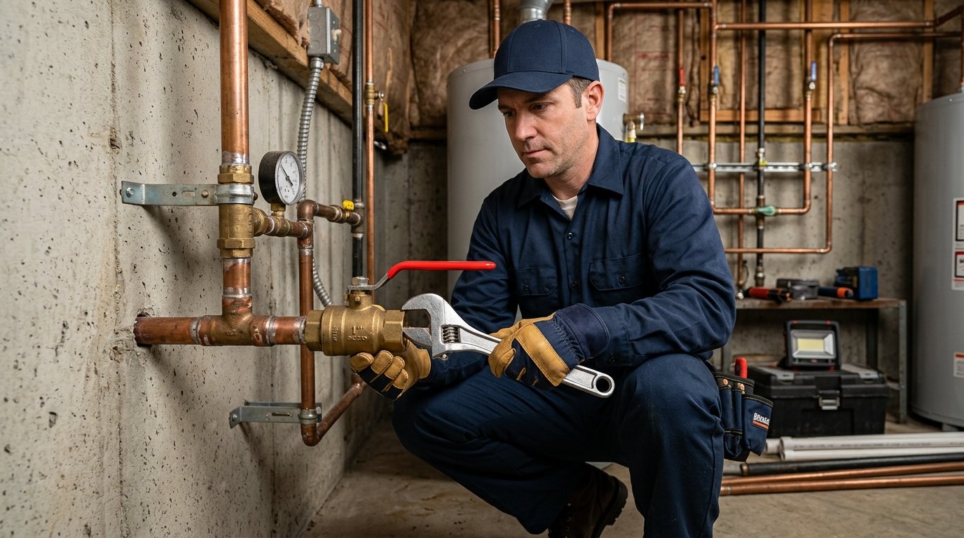
1. Gas Pressure Physics: The Three-Pressure Cascade in Commercial Facilities
A commercial gas distribution system does not operate at a single uniform pressure. It is an engineered pressure cascade designed to move high BTU volumes through modest pipe diameters before stepping down to delicate appliance burner limits.
In the City and County of Broomfield, utility providers like Xcel Energy deliver natural gas from the street main into commercial utility meters at three distinct delivery classes:
- Standard Low-Pressure Utility Delivery: 7.0″ to 14.0″ Water Column (approx. 0.25 to 0.50 PSI). Found in older light-commercial strip centers built prior to 1990.
- Medium-Pressure Utility Delivery (Elevated Delivery): 2.0 PSI (55.4″ Water Column). The modern standard for commercial kitchens, multi-family central boiler plants, and retail centers. Moving gas at 2 PSI allows plumbers to use 1-1/4″ or 1-1/2″ supply risers instead of bulky 3″ or 4″ low-pressure headers, saving tremendous structural space and piping installation costs.
- High-Pressure Industrial Delivery: 5.0 to 10.0+ PSI. Reserved for heavy manufacturing campuses, commercial asphalt batch plants, and large district campus heating boilers.
Commercial cooking equipment, gas-fired hydronic boilers, unit heaters, and domestic water heaters cannot tolerate 2 PSI. Standard commercial appliances operate on low manifold pressure:
- Natural Gas Appliance Manifolds: 3.5″ to 5.0″ Water Column (0.12 to 0.18 PSI).
- Propane (LP) Appliance Manifolds: 10.0″ to 11.0″ Water Column (0.36 to 0.40 PSI).
If 2 PSI (55″ WC) surges past a failing regulator and hits a commercial gas fryer combination control valve rated for a maximum inlet pressure of 1/2 PSI (14″ WC), the internal safety shutoff solenoid blows out, internal diaphragm gaskets tear, and uncontrolled raw gas sprays past the burner orifices.
2. Mechanical Anatomy: How the Internal Force Balance Governs Flow
A gas regulator is not an electrically controlled valve. It is a purely mechanical, self-contained feedback loop operating under Newton’s laws of motion.
Inside the cast aluminum or cast iron regulator body, three mechanical components continuously balance opposing forces:
- The Calibrated Loading Spring: Located in the upper spring tower. It exerts an adjustable downward mechanical force ($F_{\text{spring}}$) upon the top diaphragm plate, forcing the valve disc open away from the orifice seat.
- The Flexible Elastomeric Diaphragm: A molded nitrile (Buna-N), neoprene, or fluorocarbon flexible disc clamped between the upper atmospheric housing and lower gas body. Downstream gas pressure enters underneath the diaphragm, exerting an upward lifting force ($F_{\text{gas}}$) equal to pressure multiplied by effective diaphragm area.
- The Orifice & Regulating Disc: Connected to the diaphragm stem via a lever linkage or direct axial shaft. When downstream appliances ignite and consume gas, line pressure drops. The spring pushes down, pulling the valve disc away from the orifice to admit more gas. When appliances shut off, downstream pressure builds under the diaphragm, driving the disc tightly into the orifice seat to throttle or halt the flow.
The Steady-State Equilibrium Equation
Under stable flow, the regulator maintains force equilibrium:
Where:
- $F_{\text{spring}}$ = Downward mechanical thrust of the compressed adjustment spring (pounds-force, lbf)
- $P_{\text{downstream}}$ = Downstream delivery pressure acting on the lower diaphragm surface (PSIG)
- $A_{\text{diaphragm}}$ = Effective surface area of the flexible elastomeric diaphragm ($in^2$)
- $F_{\text{seat\_friction}}$ = Mechanical frictional resistance of the stem guide and pivot pins (lbf)
Notice the mathematical vulnerability. If $A_{\text{diaphragm}}$ ruptures, the opposing pneumatic force $(P_{\text{downstream}} \times A_{\text{diaphragm}})$ instantly collapses. The powerful loading spring drives the valve wide open. Full line delivery pressure surges downstream into delicate equipment, while high-velocity fuel gas exhausts into the upper atmospheric chamber.
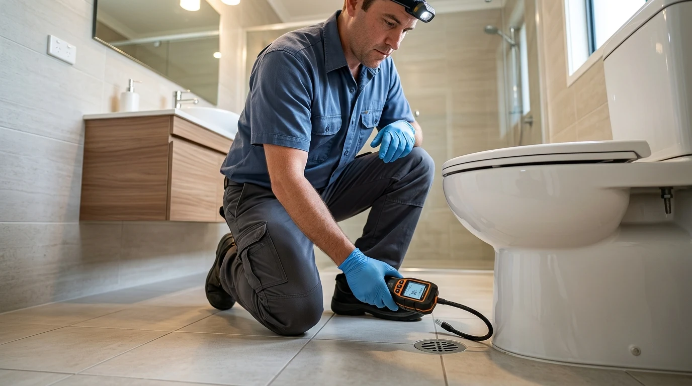
3. Direct-Acting vs. Pilot-Operated Regulators: Engineering Comparison
Not all commercial regulators utilize the same internal architecture. Depending on volume demand and line pressure, engineers select between two primary categories:
| Design Parameter | Direct-Acting Regulators (e.g., Maxitrol 325 Series) | Pilot-Operated Regulators (e.g., Fisher 627 / Mooney Flowgrid) |
|---|---|---|
| Operating Principle | Downstream pressure acts directly upon the main diaphragm opposing a mechanical spring. | A small secondary pilot regulator senses downstream pressure and loads/unloads a heavy primary rubber boot or piston. |
| Capacity Range | 150 to 2,500 SCFH (Up to 2.5 Million BTU/hr) | 2,500 to 100,000+ SCFH (5 to 100+ Million BTU/hr) |
| Lockup Sensitivity | Prone to droop (10-15% pressure drop under max load). | Extremely tight lockup within ±1% of setpoint across entire firing curve. |
| Response Time | Instantaneous mechanical response (Milliseconds). | Slight lag (100 to 300 ms) while pilot bleeds operating gas volume. |
| Diaphragm Failure Consequence | Main valve fails wide open. Gas escapes through upper vent limiter. | Can be configured fail-open or fail-closed depending on pilot piping topology. |
| Common Commercial Use | Individual kitchen equipment lines, boiler unit drops, RTU curb connections. | Main building gas service entrance, central campus central heating plants. |
4. Diaphragm Rupture Mechanisms: Why Flexible Membranes Tear
Why does a durable synthetic rubber diaphragm fail inside a sealed metal housing?
In our decades of commercial plumbing inspections across Broomfield and the Front Range, we identify four root causes behind diaphragm perforation:
1. High-Frequency Cycling & Flex Fatigue
Commercial cooking kitchens operate under violent load swings. Six fryers, three salamanders, two ranges, and a double convection oven kick on and off hundreds of times every dinner service. Each time a fast-acting solenoid snaps open, downstream pressure drops abruptly. The diaphragm flexes downward violently, then rebounds.
Over five to eight years of continuous operation, that cyclic bending causes mechanical fatigue along the outer convolution bead of the nitrile membrane. Microscopic stress fractures coalesce into a radial tear.
2. Upstream Gas Contaminants & Chemical Attack
Natural gas is not 100% clean methane. It carries trace hydrocarbons, condensable pentanes, odorant mercaptans, and compressor lubricant carryover from utility transmission stations.
In cheap aftermarket diaphragms, these petroleum distillates leach the plasticizers from the rubber matrix. The rubber loses elasticity, hardens, turns brittle, and cracks during normal pressure modulation.
3. Severe Gas Water Hammer from Fast-Closing Solenoids
When large commercial equipment gas valves snap shut in under 50 milliseconds, momentum in the flowing gas column produces an acoustic gas shock wave—a fuel gas water hammer.
That instantaneous pressure wave bounces back into the regulator body, hammering the bottom of the diaphragm with spikes exceeding three to four times operating pressure. This mechanical shock tears diaphragms off their central clamping washer.
4. Sub-Zero Freezing & Diaphragm Stiffening
Regulators mounted outdoors or in unconditioned rooftop enclosures face Colorado winter temperatures plunging to -15°F. Standard commercial nitrile stiffens dramatically below zero degrees. If moist gas condenses inside the housing, ice crystals puncture the stiffened elastomer.
5. Atmospheric Venting & Vent Limiter Operations: IFGC Section 410
A gas regulator must breathe. As the diaphragm moves upward, air inside the upper bonnet must escape. As the diaphragm moves downward, room air must enter. If you plug the vent port, the regulator becomes hydraulically locked and ceases to regulate pressure.
To allow air breathing while protecting human life, plumbers use one of two code-compliant methods governed by IFGC Section 410.3:
| Venting Method | Code Standard (IFGC / ANSI) | Maximum Inlet Pressure Allowed | How It Operates in an Emergency | Permitted Installation Locations |
|---|---|---|---|---|
| Vent Limiting Device (Vent Limiter) | ANSI Z21.80 / CSA 6.22 | Max 2.0 to 5.0 PSI (Depending on listing) | Internal precision aluminum/brass ball check floats up and seals the vent port if gas velocity surges above 2.5 SCFH. Allows tiny bleed (max 2.5 SCFH) into room. | Indoor commercial kitchens and mechanical rooms with adequate air volume. Must be mounted vertically upright only. |
| Dedicated Outdoor Vent Piping | IFGC Section 410.3 & NFPA 54 | Unlimited (Standard for all commercial loads > 5 PSI) | Full-size steel or copper pipe routed continuously to building exterior, terminating in a downward-facing insect-screened hood. | Mandatory for all regulators lacking a vent limiter, all regulators over 5 PSI inlet, and all underground/sub-slab installations. |
The Deadly Mistake: Sideways or Upside-Down Vent Limiters
A vent limiter is purely a mechanical gravity ball check.
Inside the tiny threaded brass fitting, a precision lightweight ball rests at the bottom of a chamfered cage. When the regulator breathes slowly, ambient air passes freely around the ball. But if the diaphragm tears and high-pressure gas rushes outward, the gas velocity lifts the ball against a machined upper seat, sealing the vent to less than 2.5 cubic feet per hour (SCFH) of gas leakage—well within safe mechanical room ventilation limits.
The catch?
Gravity must keep that ball resting in the bottom of its cage.
If an untrained technician installs the gas regulator on a vertical gas riser so that the vent limiter points horizontally sideways or upside down, gravity pulls the ball away from the seat or wedges it in the corner. When the diaphragm tears, the ball check never seats. Gas blasts unimpeded through the vent hole at full line pressure.
Dedicated Vent Line Sizing per IFGC Section 410.3
When indoor regulators cannot use vent limiters, dedicated steel or copper vent piping must be routed to the outdoors. The vent pipe diameter must equal the regulator vent connection diameter (typically 3/8″, 1/2″, or 3/4″ NPT) for runs up to 30 feet.
For long runs exceeding 30 feet, pipe diameter must increase by one nominal size for every additional 30 feet of equivalent length to prevent back-pressure accumulation from choking diaphragm response. Elbows add substantial equivalent length:
- 3/4″ 90-degree black malleable iron elbow = 2.06 feet equivalent length
- 1″ 90-degree black malleable iron elbow = 2.62 feet equivalent length
- Terminal outlet insect screen = 1.50 feet equivalent length
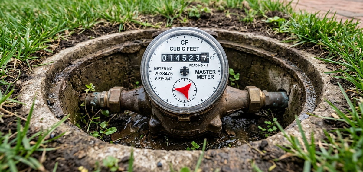
6. Lockup Dynamics & Debris-Induced Creeping Pressure Spikes
What is “lockup” pressure, and why does it destroy commercial equipment?
When every commercial cooking range, pizza oven, or boiler burner shuts off at 11:00 PM, gas flow through the regulator drops to exactly zero.
In that moment, the regulator must achieve positive mechanical lockup: the rubber valve seat must seal completely bubble-tight against the metal orifice knife-edge, holding line pressure back even with zero gas consumption.
Normal Lockup vs. Creeping Failure
Under normal conditions, lockup pressure rises roughly 10% to 20% above the operating setpoint:
- Operating setpoint under flow: 7.0″ WC
- Healthy static lockup pressure: 8.0″ to 8.5″ WC (Stabilizes and stops climbing)
Now consider what happens when pipe scale, black iron mill slag, or over-applied pipe dope flakes off upstream pipe threads and lodges directly on the orifice seat.
The valve disc cannot close that final 0.010 inches.
Overnight, high upstream pressure (2 PSI / 55″ WC) slowly leaks past the contaminated seat. Downstream pressure creeps up: 10″ WC… 20″ WC… 35″ WC… 55″ WC.
By 6:00 AM, the downstream gas piping has equalized with the incoming main. When the line cook turns the knob on a commercial broiler, the safety valve fails to open, or worse, high-pressure gas rushes into the burner chamber, creating a frightening delayed-ignition fireball that blows open the oven doors.
7. Front Range Atmospheric Physics: Altitude Derating at 5,400+ Feet
Plumbing at 5,400 feet above sea level follows different physical rules than sea level.
In Broomfield, atmospheric barometric pressure averages roughly **12.1 to 12.3 PSI**, compared to 14.7 PSI at sea level. This 2.4 PSI atmospheric reduction alters fuel-gas density, atmospheric chamber reference pressures, and combustion stoichiometry.
The Exterior Vent Frost-Capping Disaster
When regulators are vented outdoors through exterior walls, the pipe terminus must be fitted with a weather-resistant, downward-facing elbow containing an **18-mesh stainless steel or brass insect screen**.
During Colorado winter blizzards, freezing fog, blowing powder snow, and sub-zero wind chills create a deadly hazard:
- Snow Drift Burial: A snow drift piles four feet against the north commercial exterior wall, completely burying the regulator vent termination.
- Condensation Frost Capping: Natural gas contains microscopic traces of water vapor. As warm, moist gas breathes through an uninsulated steel vent line penetrating an unheated exterior wall, the water vapor freezes instantly on the fine mesh screen. Ice forms a hermetic seal over the vent opening.
Once the atmospheric vent is plugged with ice, atmospheric air cannot enter the top chamber. As downstream appliances turn on and pull gas, a vacuum forms above the diaphragm. The diaphragm is sucked upward, preventing the valve from opening.
The entire facility loses gas pressure. Boilers lockout with low-gas-pressure error codes. Commercial kitchens go dark in the middle of lunch service.
8. Step-by-Step Master Plumber Diagnostics: Manometer Testing Protocols
Never diagnose a gas leak with your nose alone. Master plumbers use precision digital dual-port differential manometers capable of measuring resolution down to 0.01 inches water column.
| Diagnostic Step | Plumbing Tool / Instrument | Acceptable Benchmark Reading | Failure Indicator & Action Required |
|---|---|---|---|
| 1. Static Upstream Pressure | Digital Manometer (High-port) | Within utility contract spec (e.g., 2.0 to 5.0 PSI ±5%) | Pressure below 1.5 PSI indicates upstream utility meter regulator failure or frozen gas service line. |
| 2. Atmospheric Vent Sniff & Bubble Test | Snoop Liquid Leak Detector & Combustible Gas Sniffer (PPM) | 0.00 PPM gas detectable at vent outlet; zero bubbling on fluid film. | Continuous bubbles indicate ruptured internal diaphragm. Replace regulator immediately; do not attempt field diaphragm patching. |
| 3. Operating Delivery Pressure | Differential Manometer on downstream test port | Natural Gas: 3.5″ to 7.0″ WC Propane: 10.0″ to 11.0″ WC |
Pressure droop exceeding 1.5″ WC during full-fire boiler load indicates undersized regulator orifice or restricted inlet filter screen. |
| 4. Static Lockup Test | Dual-port Manometer with full equipment shutoff | Max 10% to 20% rise above operating pressure (Holds steady indefinitely). | Pressure continues to climb past 12″ WC toward line pressure. Indicates debris on seat, cut elastomer disc, or warped valve stem. |
| 5. Vent Limiter Ball Freedom | Visual & Acoustic Shake Check | Audible metallic rattle when shaken vertically. Free travel inside cage. | If stuck, gummy with restaurant cooking grease, or corroded, replace vent limiter. Clean air passage is life-safety critical. |
9. Commercial Pipe Sizing Math: Calculating Orifice Flow Capacity
Regulators cannot be sized simply by matching pipe diameter. An 1-1/4″ pipe can deliver wildly different capacities depending on the internal orifice diameter and inlet pressure drop.
To determine required regulator capacity ($Q$) in standard cubic feet per hour (SCFH), calculate total connected equipment firing rate:
For Colorado natural gas along the Front Range, average heating value is approximately **1,000 BTU per cubic foot**:
For a commercial facility operating:
- Two 500,000 BTU/hr hydronic boilers = 1,000,000 BTU/hr
- One 250,000 BTU/hr commercial domestic hot water heater = 250,000 BTU/hr
- Two 120,000 BTU/hr commercial kitchen ranges = 240,000 BTU/hr
- Total Load: 1,490,000 BTU/hr
If a contractor mistakenly installs a standard 600 SCFH regulator on that 1-1/4″ header, pressure will catastrophically collapse every time the boilers kick on simultaneously with the kitchen equipment.
10. Real-World Case Study: Broomfield Restaurant Flashback Investigation
In November 2025, an emergency dispatch brought our master plumbing crew to an upscale restaurant off US-36 in Broomfield. The kitchen manager reported intermittent, terrifying detonations inside their commercial stone-hearth pizza oven upon morning ignition.
Our forensic investigation uncovered the root cause in thirty minutes:
- The Symptom: Overnight, static pressure downstream of the 2-PSI-to-7″-WC appliance regulator climbed to 32″ WC (1.15 PSI)—more than double the safe operating limit.
- The Autopsy: We unbolted the regulator body and extracted the valve seat assembly. Lodged tightly between the synthetic valve disc and the stainless steel orifice was a 1/8″ curly shaving of steel pipe thread shavings left behind by an unqualified installer who failed to ream the pipe ends.
- The Outcome: The debris prevented full lockup. Over eight hours of overnight shutdown, line pressure slowly pressurized the manifold. In the morning, turning the pilot knob unleashed a high-pressure jet of fuel that pooled inside the oven cavity before detonating upon contact with the hot ceramic elements.
We rebuilt the station with a heavy-duty Maxitrol 325-7A regulator, installed an upstream 50-mesh particulate sediment strainer, added a vertical drip leg sediment pocket per IFGC Section 408, and conducted an ASME-standard 15-minute high-pressure decay test. The facility reopened safely for lunch.
11. Emergency Replacement & IFGC Section 406 Pressure Testing Protocols
When replacing a commercial gas regulator, licensed master plumbers adhere to rigid code protocols:
- Full Mechanical LOTO: Close the upstream quarter-turn gas ball valve. Apply lockout/tagout padlock to the valve lever. Vent residual line gas through an outdoor purge line.
- Install Upstream Sediment Trap: Under IFGC Section 408.4, every appliance regulator must have an upstream sediment trap (drip leg) formed by a tee fitting with a capped nipple descending at least 3 inches below the run. This catches metal scale before it enters the regulator.
- Proper Vent Limiter Orientation: Ensure the regulator is installed in a strictly horizontal run with the vent limiter pointing vertically straight up toward the ceiling.
- IFGC 406 High-Pressure Air Decay Test: Before introducing fuel gas, isolate downstream appliances and pressurize the new pipe assembly with dry nitrogen or compressed air to at least 10 PSI on a calibrated test gauge. The pressure must hold rock solid for a minimum of 15 minutes with zero needle movement.
- Manometer Delivery Verification: Introduce gas slowly. Ignite connected appliances one by one until operating at 100% full fire. Verify manifold pressure holds between 5.0″ and 7.0″ WC without droop or harmonic resonance.
12. Documentation, Tagging & NFPA 54 Annual Verification Logs
Commercial code enforcement across Adams and Boulder counties requires rigorous proof of ongoing maintenance for all fuel gas equipment operating above standard residential pressures.
Under IFGC Section 107.2 and NFPA 54 Section 5.12, commercial property managers must maintain an on-site mechanical inspection log for every line pressure regulator and emergency shutoff station. Each regulator must bear an indelible weather-resistant inspection tag recording:
- Date of Commissioning or Rebuild: Exact date internal diaphragm and seat were replaced.
- Measured Lockup Pressure: Precise digital manometer reading recorded at zero-flow lockup.
- Full-Fire Flow Pressure: Dynamic delivery pressure under simultaneous 100% equipment fire.
- Vent Limiter Freedom Verification: Confirmation that gravity ball check moves freely without binding.
- Master Plumber License Number: State of Colorado master plumbing contractor registration.
When fire marshals or mechanical inspectors perform annual commercial life-safety audits, an un-tagged regulator or a missing maintenance log can trigger immediate red-tag notices, shutting down your gas service until certified compliance testing is documented.
Frequently Asked Questions About Commercial Gas Regulators
Why is my gas regulator vent whistling or making a buzzing noise?
A buzzing or whistling regulator usually indicates rapid diaphragm vibration (hunting) caused by high gas velocity through an undersized orifice, or harmonic resonance between the loading spring and downstream pulsating burner solenoids. In some cases, foreign debris stuck between the valve disc and seat causes high-velocity turbulence.
Can you install a gas regulator indoors without running a vent pipe outside?
Yes, but ONLY if the regulator is specifically listed with an approved vent limiting device (ANSI Z21.80/CSA 6.22) and operating at an inlet pressure of 2 PSI or 5 PSI maximum. The regulator must be installed in an upright horizontal pipe run so the vent limiter points vertically straight up.
How do I know if my gas regulator diaphragm has ruptured?
The clearest sign is raw natural gas or propane continuously escaping from the vent limiter or exterior vent line. Additionally, downstream gas pressures will surge dangerously high, causing appliances to roar loudly, soot up burner assemblies, or lock out on high-gas-pressure limit switches.
What is the difference between an appliance regulator and a line pressure regulator?
A line pressure regulator reduces utility delivery pressure down to an intermediate piping level. An appliance regulator is mounted directly upstream of specific equipment to fine-tune burner manifold pressure to exact specifications.
Who do I call for emergency commercial gas regulator replacement in Broomfield, CO?
Call Broomfield Emergency Plumber 24/7 at (303) 647-3363. Our licensed master plumbers specialize in commercial gas manifolds, NFPA 54 compliance, high-capacity regulator replacements, and emergency IFGC pressure testing across the Front Range.
Smelling Gas or Experiencing Pressure Surges in Your Commercial Facility?
Never take chances with commercial gas pressure assemblies. Our licensed Colorado master plumbers provide 24/7 emergency gas line repairs, digital manometer lockup diagnostics, and rapid regulator replacement across Broomfield, Boulder, and Adams County.