
Master Plumber Engineering Advisory: Closed-Loop Domestic Water Pressurization
Throughout modern residential construction in Broomfield, Westminster, Boulder, and surrounding Colorado Front Range municipalities, domestic potable water supply systems operate as strictly closed plumbing loops. The universal installation of municipal check valves, backflow containment assemblies at utility meters, and whole-house pressure reducing valves (PRVs) permanently prevents thermally expanded water from expanding backward into public mains. When a 40, 50, or 75-gallon water heater fires and elevates municipal water from 45 degrees Fahrenheit to 125 degrees Fahrenheit, the water expands by approximately 2 to 3 percent in volume. In an unmitigated closed system, this incompressible hydraulic expansion causes rapid, dangerous hydrostatic spikes exceeding 150 PSI, rupturing water heater tank welds, destroying appliance solenoid valves, and triggering catastrophic temperature and pressure (T&P) relief valve blowouts. This technical guide provides licensed engineering analysis, failure diagnostics, pre-charge sizing formulas, and IPC compliance protocols for potable thermal expansion tanks.
1. The Thermodynamics of Thermal Expansion in Potable Water Systems
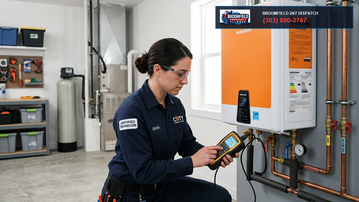
Water is an essentially incompressible physical liquid. Unlike gases, whose molecules can be compressed into significantly smaller volumetric spaces under moderate pneumatic forces, liquid water molecules under mechanical confinement exhibit an exceptionally high bulk modulus of elasticity (approximately 312,000 PSI or 2.15 GPa at standard ambient temperatures). This fundamental thermodynamic property governs every domestic water distribution network across the Colorado Front Range. When municipal water enters a residential structure from subterranean utility distribution conduits maintained by the City and County of Broomfield, Denver Water, or the City of Boulder, its temperature typically hovers between 40 degrees Fahrenheit during freezing winter snowmelt cycles and 55 degrees Fahrenheit during peak summer months.
Inside a residential storage tank water heater, high-output natural gas burners (rated at 36,000 to 50,000 BTU/hr) or electric resistance immersion elements rapidly transfer thermal energy into the contained water column. Standard domestic sanitation guidelines and legionella prevention standards establish operational setpoints between 120 degrees Fahrenheit and 140 degrees Fahrenheit. As thermal energy transfers into the fluid, the kinetic excitation of the hydrogen and oxygen molecules causes them to vibrate more vigorously and separate, decreasing fluid density and driving a volumetric expansion rate of approximately 0.000214 per degree Fahrenheit increase. For a conventional 50-gallon residential water heater heating water through an 80-degree Fahrenheit delta temperature swing (from 45 degrees to 125 degrees Fahrenheit), the total physical liquid volume expands by approximately 0.85 to 1.15 gallons of additional water.
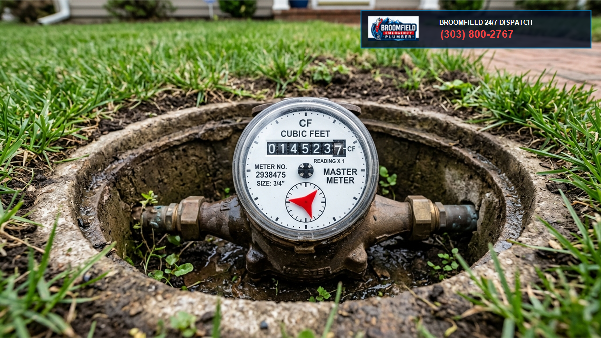
In historically open municipal water systems built prior to modern containment mandates, this extra gallon of expanded fluid simply migrated backward through the service lateral into the city main without consequence. However, under modern public health and plumbing codes, cross-connection control measures have sealed the boundary between private building infrastructure and public utility infrastructure. A municipal dual-check valve located at the outdoor water pit meter or an internal whole-home pressure reducing valve equipped with an internal check valve acts as a mechanical check gate. The expanded fluid has nowhere to go. Because the plumbing pipes, fittings, and appliances are rigid structures, that single extra gallon of unabsorbed fluid causes immediate, severe hydrostatic pressure spikes. An unmitigated residential system running at a baseline static pressure of 60 PSI will effortlessly spike above 150 PSI to 180 PSI within 20 minutes of water heater burner activation.
2. International Plumbing Code (IPC) & Colorado Front Range Regulatory Framework
Municipal building inspection departments throughout Colorado enforce stringent regulations regarding thermal expansion control. Under the International Plumbing Code (IPC Section 607.3) and the Uniform Plumbing Code (UPC Section 608.3), any potable water distribution system equipped with a backflow preventer, check valve, pressure reducing valve, or any device that creates an unvented closed loop must incorporate an approved mechanical device for controlling thermal expansion.
In Broomfield, Westminster, Arvada, Louisville, and Lafayette, municipal plumbing inspectors will automatically issue a code violation or red-tag inspection failure on water heater replacements or major plumbing alterations if an approved potable thermal expansion tank is absent, improperly sized, or unanchored. The code mandates that the thermal expansion device must be designed and certified to ASME or NSF/ANSI 61 and 372 standards, rated for continuous potable drinking water contact, and capable of withstanding maximum system operating pressures without exceeding the pressure limits of the system components.
| Plumbing Code Standard | Mandated Mechanism | Operational Pressure Limit | Colorado Municipal Enforcement |
|---|---|---|---|
| IPC Section 607.3 | Potable Expansion Tank / Auxiliary Relief | Must not exceed 80 PSI static working load | Mandatory on all closed loops in Broomfield & Boulder Counties |
| UPC Section 608.3 | Diaphragm Expansion Tank on Cold Supply | Sized to absorb calculated volumetric delta | Required upon water heater permit final inspection |
| ASME Section IV | Commercial Expansion Vessel Construction | Rated to 125 or 150 PSI working pressure | Mandatory on commercial boilers and multi-family water systems |
| NSF/ANSI 61 / 372 | Lead-Free Potable Barrier Certification | Zero toxic leaching into drinking supply | Standard requirement for all residential installations |
3. Internal Anatomy & Operating Mechanics of Potable Diaphragm Expansion Tanks
A residential potable thermal expansion tank is a specialized hydraulic pressure vessel engineered to provide an artificial, compressible pneumatic cushion within an otherwise rigid, incompressible piping system. The vessel consists of a deep-drawn high-tensile carbon steel outer shell finished with an electrostatically applied polyurethane enamel coating to resist atmospheric oxidation in humid basements and mechanical rooms.
Internally, the vessel is divided into two distinct chambers separated by a flexible, impermeable elastomeric barrier. In superior commercial-grade potable tanks, this barrier is fabricated from heavy-duty butyl rubber or ethylene propylene diene monomer (EPDM) compound. The lower chamber connects directly to the potable water distribution piping via a male NPT stainless steel or forged brass threaded connection. To maintain NSF 61 potable purity and prevent metallic corrosion, the interior water-side steel chamber is lined with an inert polypropylene liner.
The upper chamber contains a captive sealed volume of atmospheric air or dry nitrogen gas, charged through an external brass Schrader tire-style valve located at the top of the tank domed cap. When the plumbing system rests in an unheated, static state, the air charge behind the flexible diaphragm exerts mechanical force against the barrier, pressing it against the lower water port. As the water heater activates and the fluid column expands, the incompressible water pushes into the water chamber, flexing the rubber diaphragm upward and compressing the air pocket. Because gases follow Boyle’s Law ( V_1 = P_2 V_2$), the compressed air pocket absorbs the expanded water volume while maintaining system hydrostatic pressures safely within the standard 60 PSI to 75 PSI operating envelope, preventing pressure surges from ever reaching the 150 PSI relief threshold of the water heater safety valves.
4. Mathematical Sizing Principles & Elevation Adjustments for Colorado
One of the most widespread errors encountered by master plumbers during residential diagnostics across the Colorado Front Range is improperly sized or incorrectly pre-pressurized expansion tanks installed by unqualified handymen. Installing a tank directly out of the manufacturer box without measuring and matching the baseline residential supply pressure creates immediate operational failure.
The required total volume of a potable thermal expansion tank ($) is calculated using the standard thermodynamic expansion equation:
V_t = \frac{V_e}{1 – \left(\frac{P_{initial} + 14.7}{P_{max} + 14.7}\right)}
Where:
- $ = Net volumetric expansion of the water column in gallons ( = V_0 \times \Delta e$, where $ is total water heater storage capacity and $\Delta e$ is the coefficient of thermal expansion for the temperature delta).
- {initial}$ = Baseline static cold water supply pressure entering the structure in gauge PSI (must match the pneumatic pre-charge of the tank air bladder).
- {max}$ = Maximum allowable design pressure of the residential system (standard plumbing engineering sets this at 80 PSI maximum per IPC code, well below the 150 PSI T&P valve rating).
- 14.7 = Atmospheric pressure at sea level in absolute PSI. (Critical Colorado Adjustment: At Broomfield’s elevation of 5,430 feet and Boulder’s 5,328 feet, standard barometric atmospheric pressure drops to approximately 12.0 to 12.2 PSI absolute. Plumbers must adjust pneumatic calculations to prevent under-damping!).
For a standard 50-gallon water heater in Broomfield where municipal incoming static pressure is regulated to 65 PSI by a whole-house PRV:
- Water heating from 45 degrees to 135 degrees Fahrenheit expands by 2.2 percent: = 50 \times 0.022 = 1.10\text{ gallons}$.
- Acceptance factor at 65 PSI static and 80 PSI peak: – [(65 + 12.1) / (80 + 12.1)] = 1 – (77.1 / 92.1) = 1 – 0.837 = 0.163$.
- Minimum tank displacement volume required: = 1.10 / 0.163 = 6.74\text{ gallons}$.
In this scenario, a miniature 2.0-gallon expansion tank (commonly sold in retail home improvement stores) will completely bottom out its diaphragm long before the water heater reaches its thermal peak, resulting in pressure spikes above 100 PSI. A licensed master plumber will specify a minimum 4.5 to 7.0-gallon expansion tank (such as an Amtrol Therm-X-Trol ST-12 or Watts PLT-12) to ensure the bladder operates within its elastic damping range.
5. Five Critical Failure Modes of Potable Thermal Expansion Tanks
Thermal expansion tanks possess an operational design lifespan of approximately 5 to 8 years, heavily dependent upon incoming municipal water chemistry, chlorine concentrations, baseline static water pressures, and operational cycling frequencies. When a tank degrades, it exhibits distinct physical, mechanical, and hydraulic failure modes:
Failure Mode 1: Elastomeric Diaphragm Rupture & Internal Waterlogging
The most frequent fatal failure mode is the physical rupture, tearing, or microscopic fatigue cracking of the internal butyl rubber diaphragm. Over years of thermal cycling, the rubber membrane flexes millions of times. Municipal water treated with chlorine or chloramines by local utilities accelerates the oxidative degradation and embrittlement of the elastomer. Eventually, a microscopic perforation forms. Because the compressed air behind the diaphragm is under high pressure, air slowly diffuses into the water stream, and high-pressure water floods the pneumatic air chamber. Within hours, the tank becomes completely waterlogged. With zero compressible gas volume remaining, the tank loses 100 percent of its shock-absorbing capacity.
Failure Mode 2: Schrader Valve Core Corrosion & Pneumatic Pressure Depletion
Like an automotive tire, the brass Schrader valve at the top of the expansion vessel relies on an internal spring-loaded elastomer pin valve to contain the air pre-charge. In humid mechanical spaces or where ambient temperatures fluctuate, the Schrader valve core can corrode, or microscopic debris can prevent the seat from sealing. Over a 12 to 24-month span, the air charge bleeds down to zero PSI. Under incoming water pressure, the diaphragm is pinned against the top of the vessel, resulting in effective waterlogging even though the rubber bladder has not torn.
Failure Mode 3: Dielectric Galvanic Corrosion at the Threaded Nipple
Expansion tanks are manufactured with carbon steel or cast stainless connections. When an installer connects a carbon steel expansion tank directly to a residential copper cold water supply line without an approved dielectric union or high-grade brass adapter, a aggressive galvanic corrosion cell establishes. Electrical potentials between dissimilar metals cause accelerated galvanic oxidation of the steel threads. Over time, rust blisters form, restricting water entry into the tank and eventually causing catastrophic thread shearing and high-pressure flooding.
Failure Mode 4: External Condensation Shell Corrosion & Perforation
In Colorado basements during humid summer thunderstorms or in poorly ventilated utility rooms, continuous cold municipal water entering the base of the expansion tank chills the exterior steel shell below the dew point of the surrounding ambient air. Condensation forms continuously across the painted steel surface. If the tank is installed in contact with masonry walls or in dusty environments, moisture becomes trapped, slowly eating through the enamel coating and oxidizing the steel shell from the outside in until the wall thins and pinhole leaks spray across the mechanical space.
Failure Mode 5: Mechanical Fatigue & Thread Shearing Due to Lack of Structural Support
A standard 4.5-gallon expansion tank weighs approximately 8 pounds when dry. However, when the diaphragm flexes or if the tank waterlogs, the vessel fills with water, increasing its total operational weight to over 45 pounds. If the tank is threaded horizontally into a standard 3/4-inch rigid copper pipe tee without a dedicated expansion tank wall bracket or heavy-duty pipe strapping, the immense cantilevered mechanical load exerts intense rotational torque on the copper solder joints and fittings. Over months of thermal vibration, this shear stress induces metal fatigue cracking, resulting in full-bore pipe separation and catastrophic basement flooding.
6. Step-by-Step Field Diagnostic Workflow for Master Plumbers
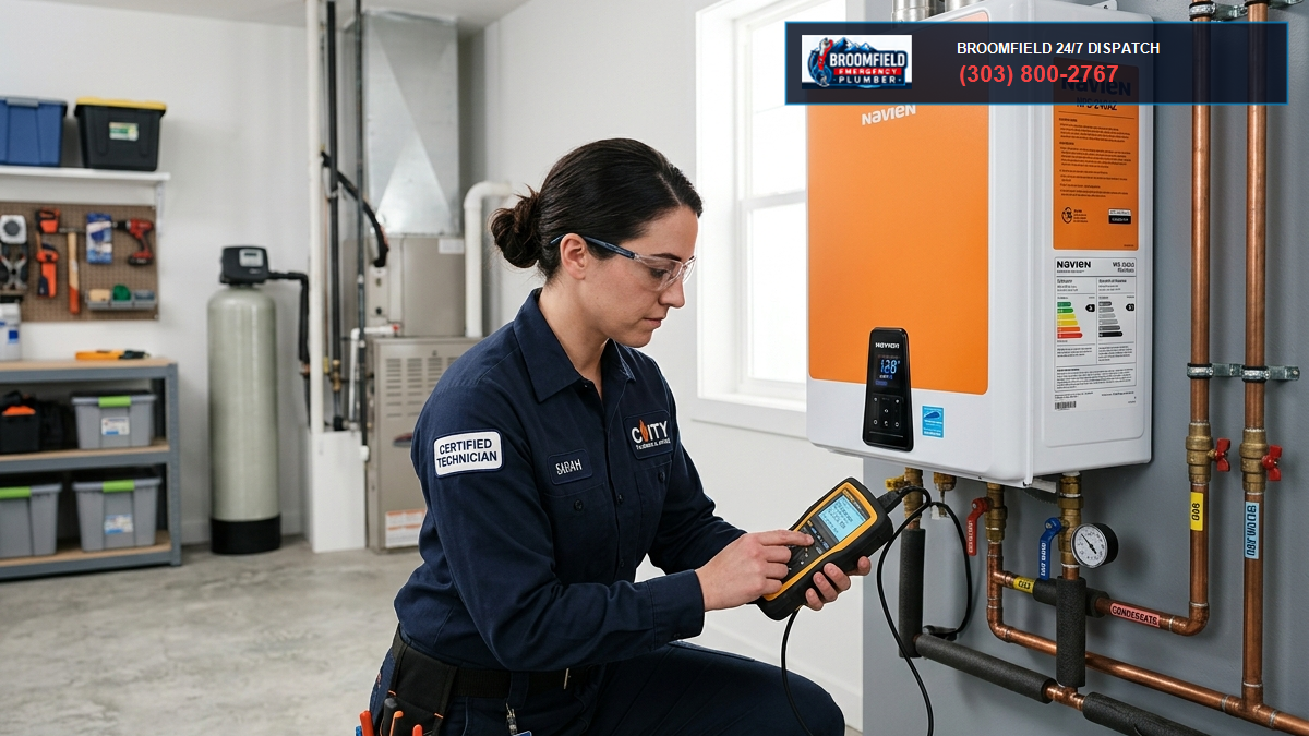
Diagnosing an expansion tank requires systematic diagnostic instrumentation. Licensed master plumbers follow an exacting 6-step testing protocol to evaluate vessel health:
- Visual Inspection for Structural & Physical Integrity: Inspect the exterior enamel shell, the threaded connection at the cold water supply tee, and the base weld for rust, scale, weeping solder, or dielectric corrosion. Inspect pipe hangers to ensure the weight of the vessel is physically supported by wall framing or pipe struts rather than cantilevered on bare copper tubing.
- Acoustic Resonance / Tap Diagnostics: Using a metallic screwdriver handle or small wrench, gently tap the upper domed section of the tank (air chamber) and the lower section near the water connection. A properly functioning tank will emit a clear, hollow ring at the top (indicating a captive air cushion) and a dull, solid thud at the bottom (indicating the water presence). If the entire tank produces a uniform dull thud from top to bottom, the tank is almost certainly 100 percent waterlogged.
- Schrader Valve Depression & Moisture Check: Remove the protective plastic or brass cap from the top Schrader valve. Using a blunt pin or tire pressure gauge, briefly depress the valve core stem. Diagnostic Rule: If compressed air hisses out cleanly, the diaphragm barrier remains intact. If water, moisture mist, or rusty liquid squirts out of the Schrader valve stem, the internal rubber diaphragm has ruptured completely. The tank is condemned and requires immediate replacement.
- Static Water Pressure Measurement: Thread a calibrated liquid-filled water pressure gauge onto an exterior hose bibb, laundry sink faucet, or the water heater drain valve. Ensure no water fixtures, washing machines, or irrigation systems are operating. Record baseline municipal static pressure. Across the Front Range, static pressure should strictly read between 50 PSI and 70 PSI. If static pressure exceeds 80 PSI, the home pressure reducing valve (PRV) has failed and must be rebuilt or replaced simultaneously with the expansion tank.
- Thermal Dynamic Pressure Spike Test: With the pressure gauge attached to the water heater drain valve, turn on a hot water faucet upstairs and run 10 to 15 gallons of hot water until the water heater gas burner or electric elements ignite. Shut off the faucet and observe the pressure gauge continuously as the water heater heats the cold reservoir. In a healthy system with an active expansion tank, the gauge will barely fluctuate, holding steady within 3 to 6 PSI of baseline. In a system with a failed, waterlogged expansion tank, the needle will climb relentlessly: 75 PSI, 95 PSI, 120 PSI, 140 PSI, until water begins weeping or discharging forcefully from the T&P relief valve.
- Accurate Pneumatic Pre-Charge Measurement: To measure the true pneumatic pre-charge of an expansion tank, the vessel must be isolated from water line pressure. Turn off the main water shutoff valve. Open a hot and cold fixture inside the home to completely bleed water line pressure down to 0.0 PSI. Attach a digital tire pressure gauge to the expansion tank Schrader valve. The air pressure must precisely match the home static water pressure (e.g., if the PRV delivers 65 PSI, the tank pre-charge must be pumped to exactly 65 PSI using a manual bicycle pump or portable compressor). Measuring air pressure while the tank is under hydraulic line pressure will yield a false reading identical to line pressure.
7. Destruction Caused by Unchecked Thermal Expansion in Front Range Homes
When a homeowner or property manager ignores a failing expansion tank or allows an unlicensed contractor to omit the tank during a water heater installation, the continuous hydrostatic hammering destroys expensive household appliances:
- Internal Water Heater Tank Fatigue: Glass-lined steel water heater tanks are designed with rolled dome heads and welded seams. Under repetitive thermal expansion cycling (spiking to 140+ PSI multiple times per day), the inner steel vessel physically balloons and contracts. This mechanical flexing creates microscopic fractures in the vitreous porcelain enamel glass lining, exposing raw carbon steel to hot water and accelerating corrosion, leading to premature tank rupture within 3 to 5 years.
- Washing Machine & Dishwasher Solenoid Valve Failure: Modern smart appliances incorporate delicate plastic solenoid water intake valves engineered for a maximum working pressure of 80 to 90 PSI. Hydrostatic spikes over 120 PSI crack the plastic solenoid housings, rupture internal pilot diaphragms, or cause the valves to stick open, flooding laundry rooms and modern finished kitchens.
- Toilet Fill Valve Leaks & Flapper Blowouts: High line pressure exerts excessive force against toilet ballcocks and Fluidmaster fill valves, overcoming the buoyant shutoff force and causing phantom toilet filling, high water bills, and premature flapper degradation.
- Catastrophic T&P Relief Valve Weeping & Scaling: Water heater Temperature & Pressure relief valves are calibrated to open at 150 PSI or 210 degrees Fahrenheit. When forced to act as an expansion relief mechanism every heating cycle, mineral sediment deposits on the valve seat, preventing it from resealing and creating an active scald hazard and basement water damage.
8. Master Plumber Installation Protocols & Code Compliance Checklist
Installing a replacement thermal expansion tank requires adherence to professional engineering standards. Our certified master plumbers follow strict field installation guidelines across all Broomfield and Boulder County service calls:
- Always Install on the Cold Water Inlet Supply: The expansion tank must be installed upstream of the water heater tank on the cold water supply branch, between the water heater shutoff valve and the water heater tank inlet. Installing on the hot water outlet exposes the butyl diaphragm to continuous 130+ degree water, cutting its operating lifespan in half.
- Match Pneumatic Pre-Charge to Static Water Pressure: Never install an expansion tank straight out of the box (which typically ships pre-charged to 40 PSI). If the residential PRV is set to 65 PSI, the installer must add dry compressed air to the Schrader valve until the air chamber reads exactly 65 PSI with zero water pressure on the system.
- Incorporate a Dedicated Isolation Ball Valve & Union: Code-compliant installations should include a full-port brass isolation ball valve with a drain port and a dielectric union directly beneath the expansion tank. This allows the tank to be isolated, drained, and depressurized during annual maintenance testing without shutting off the main water to the entire house.
- Provide Independent Structural Seismic & Gravity Support: Mount the expansion tank vertically in a downward-hanging or upward-standing orientation using a galvanized steel wall bracket or heavy-duty Unistrut support assembly secured directly to wood wall framing or concrete foundation anchors, isolating all hydraulic deadweight from the copper piping.
9. Comprehensive Field Case Study: Anthem Ranch Luxury Home Diagnostic (Broomfield, CO)
In October 2025, our master plumbing emergency dispatch received a service request from a multi-level custom residence in the Anthem Ranch subdivision of Broomfield. The homeowner reported a baffling series of plumbing anomalies: three separate washing machine solenoid valves had cracked and flooded the second-floor laundry room over an 18-month span, the kitchen refrigerator ice-maker supply line had burst behind custom cabinetry, and the basement water heater Temperature and Pressure relief valve routinely discharged 2 to 3 gallons of hot water onto the concrete slab around midnight every evening.
Previous handyman inspections had repeatedly replaced the T&P relief valve, assuming the valve was defective. When our master diagnostic technician arrived, we installed a multi-channel digital high-speed pressure data logger on the laundry tub bibb and an auxiliary pressure transducer on the water heater drain valve. Continuous 24-hour pressure logging revealed a textbook thermal expansion catastrophe:
- Static Municipal Baseline: The home incoming water pressure reducing valve (PRV) was delivering a stable, regulated 62 PSI during non-heating standby hours.
- Thermal Spike Dynamics: At approximately 10:45 PM, following evening showers and dishwasher operation, the high-recovery 75-gallon commercial-grade residential gas water heater initiated a full heating cycle. As the burner operated continuously for 45 minutes, system hydraulic pressure steadily climbed from 62 PSI to 85 PSI within 8 minutes, passed 120 PSI at the 20-minute mark, and peaked at a staggering 164 PSI at 11:32 PM, at which point the T&P valve cracked open under hydraulic pressure, venting water to relieve the stress.
- The Root Failure: Inspection of the existing 2.0-gallon thermal expansion tank revealed it had been installed horizontally by the original builder with zero wall bracket support. Depressing the Schrader valve produced a forceful jet of brown rusty water directly in the technician face — the internal butyl diaphragm had suffered a 4-inch tear years earlier, rendering the vessel 100 percent waterlogged. The cantilevered weight of the waterlogged vessel (over 28 pounds) had also caused the 3/4-inch copper supply tee to bow downward by nearly 15 degrees, placing the soldered joint under extreme shear stress.
Our team performed a comprehensive engineered remediation: we installed an ASME-rated 4.5-gallon Amtrol Therm-X-Trol ST-12 potable expansion tank mounted vertically downward with a dedicated heavy-duty galvanized wall mounting bracket. We incorporated a full-port lead-free brass isolation ball valve with an integral bleeder port and a dielectric union. We calibrated the tank pneumatic pre-charge to exactly 62 PSI using dry nitrogen gas to match the PRV setpoint. Follow-up digital pressure logging during consecutive full-capacity heating cycles confirmed maximum system pressure never exceeded 68 PSI. The midnight discharge ceased permanently, and the home appliances were fully safeguarded against hydraulic shock.
10. Comparative Engineering Analysis: Diaphragm vs. Bladder vs. Flow-Through Potable Vessels
Specifying the correct expansion vessel requires understanding the distinct engineering typologies available in commercial and residential mechanical plumbing:
| Vessel Architecture | Internal Barrier Design | Serviceability | Recommended Applications |
|---|---|---|---|
| Standard Diaphragm Tank | Fixed butyl rubber diaphragm crimped into center shell weld; water chamber lined with polypropylene. | Non-replaceable. Entire vessel must be replaced upon diaphragm rupture. Lifespan: 5-8 years. | Standard residential domestic water heaters (40-80 gallons). Cost-effective and highly reliable when pre-charged correctly. |
| Full-Acceptance Replaceable Bladder | Bag-type elastomeric balloon secured by top and bottom flanges; water is completely contained inside the bladder. | Field-replaceable bladder. Vessel shell can remain installed indefinitely. Lifespan: 10-15+ years. | High-demand residential mansions, multi-family apartment central water plants, and commercial hydronic/potable loops. |
| Flow-Through Anti-Legionella Vessel | Dual-port inlet/outlet diverter directing a portion of main water flow through the vessel chamber on every draw. | Prevents stagnant water dead-legs and biological bacterial biofilm growth within the expansion chamber. | Hospitals, medical clinics, senior care living facilities, and high-purity residential domestic hot water recirculation systems. |
11. Master Plumber Annual Inspection & Maintenance Protocol
Homeowners and facility managers should institute a rigorous bi-annual or annual thermal expansion vessel maintenance schedule to protect against silent failure. Because a ruptured bladder exhibits no outward visible leak until catastrophic internal waterlogging occurs, routine diagnostic testing is essential:
- Quarterly Acoustic Resonance Check: Property owners should tap the upper and lower halves of the expansion vessel once every three months. The distinct hollow acoustic chime at the top indicates a healthy air pocket. If the top sounds heavy and dull, schedule professional service immediately.
- Bi-Annual Schrader Pin Depress Test: Remove the top dust cap and quickly press the center pin for one-quarter second. If any moisture droplets escape, the internal elastomer barrier has failed.
- Annual Zero-Pressure Pneumatic Re-Calibration: During annual water heater sediment flushing, isolate the domestic water main, open hot and cold fixtures to drain line pressure down to 0 PSI, and measure the static air pre-charge using an accurate digital pressure gauge. Add dry compressed air using a manual high-pressure pump if pressure has dropped below the home PRV setpoint. Inspect the Schrader core with soapy water bubble testing to verify zero micro-leakage.
24/7 Water Heater & Expansion Tank Emergency Service in Broomfield
Is your water heater pressure relief valve dripping? Did your expansion tank feel heavy, waterlogged, or cold to the touch? High water pressure can quietly destroy your home plumbing and appliances. Contact our certified master plumbers immediately for precision pressure diagnostics, expansion tank replacements, and whole-house PRV calibrations.