
1. Executive Summary & Thermodynamics of Hydronic Radiant Heating
Hydronic radiant floor heating is widely recognized by mechanical engineers as the pinnacle of residential thermal comfort and energy efficiency. Unlike conventional forced-air furnaces that blow turbulent, dry, overheated air toward the ceiling—creating severe thermal stratification where ceilings register 78°F while floors hover at 64°F—radiant floor systems invert the thermodynamic gradient.
In a hydronic floor network, warm water circulates through continuous networks of cross-linked polyethylene (PEX) tubing embedded within concrete slabs, gypsum underlayment, or aluminum heat-transfer plates beneath hardwood and tile floors. The entire floor surface transforms into a gentle, low-temperature radiator emitting infrared thermal radiation.
Infrared radiant waves transfer energy directly to solid objects, human bodies, and furniture in the room without heating intermediate air masses first. The human body absorbs this radiant heat directly, achieving optimal comfort at room thermostat settings 3°F to 5°F lower than forced-air systems. Furthermore, hydronics eliminates blowing dust, pet dander, and allergen circulation, dramatically improving indoor environmental quality in Colorado’s arid climate.
2. PEX-a Oxygen-Barrier Tubing: Material Science & Metallurgy Protection
The lifeblood of any modern hydronic heating installation is the tubing embedded beneath finished floor surfaces. Standard potable water PEX (PEX-b or PEX-c) must never be installed in closed-loop hydronic heating systems. Standard plumbing PEX allows microscopic oxygen molecules to permeate directly through the polymer wall via molecular diffusion.
In a closed hydronic loop, ingress of atmospheric oxygen creates an aggressive corrosive environment. The dissolved oxygen rapidly oxidizes cast-iron pump impellers, carbon steel expansion tanks, brass fittings, and the high-efficiency boiler heat exchanger, producing black magnetite sludge (Fe₃O₄) that seizes circulator pumps and plugs heat exchanger tubes.
The EVOH Oxygen Barrier Mandate (DIN 4726)
Hydronic piping requires specialized tubing manufactured with an integral Ethylene Vinyl Alcohol (EVOH) oxygen barrier layer meeting DIN 4726 standards (permeation rate less than 0.32 mg/m²·day at 104°F).
- PEX-a (Engel Method): PEX-a is the gold-standard tubing for radiant floors. Manufactured by cross-linking polyethylene molecules while in an amorphous, molten state using organic peroxide, PEX-a achieves a cross-linking degree greater than 85%. This molecular architecture grants PEX-a complete “thermal memory.” If a tube is accidentally kinked during jobsite installation in freezing winter weather, the kink can be 100% repaired simply by heating the tubing with a hot air heat gun until it turns clear, allowing it to recover its original cylindrical shape without weakening the wall burst strength.
- PEX-AL-PEX (Composite Aluminum Core): Consists of an aluminum core tube sandwiched between two layers of PEX. PEX-AL-PEX provides a 100% absolute oxygen vapor barrier, zero thermal elongation (does not expand or make ticking noises in joist spaces), and holds its bend shape without spring-back, making it ideal for baseboard radiator runs and boiler mechanical room header piping.
3. Hydronic Distribution Manifolds & Hydraulic Loop Balancing
In a typical residential radiant floor installation, a home is divided into multiple heating zones (e.g., Master Bedroom, Living Room, Basement Recreation Room). Each zone is served by multiple continuous loops of 1/2-inch PEX tubing connected to a central distribution manifold.
Water is inherently lazy—it follows the path of least hydraulic resistance. If three loops connected to the same manifold have different physical lengths (e.g., Loop 1 is 150 feet, Loop 2 is 220 feet, and Loop 3 is 300 feet), hot water will rush almost entirely through the short 150-foot loop, while the 300-foot loop will suffer severe flow starvation, leaving that section of flooring freezing cold.
Loop Sizing Engineering Constraints:
- Maximum Loop Length Rule: For standard 1/2-inch PEX tubing, the maximum continuous loop length should never exceed 250 to 300 feet (including the supply and return leads to the manifold). Exceeding 300 feet creates excessive frictional head loss, requiring oversized circulator pumps that consume excessive electrical power.
- Loop Length Parity: Mechanical designers strive to balance loop lengths within 10% of each other on the same manifold.
- Flow Meter Balancing: Precision manifolds feature integrated visual rotameters (sight-glass flow meters). By adjusting the micro-balancing needle valve on the return rail, the technician sets the exact flow rate (typically 0.4 to 0.8 GPM per loop) calculated by hydraulic software to deliver the designed BTU/hr heat flux.
4. High-Efficiency Condensing Combi Boilers & Primary/Secondary Piping
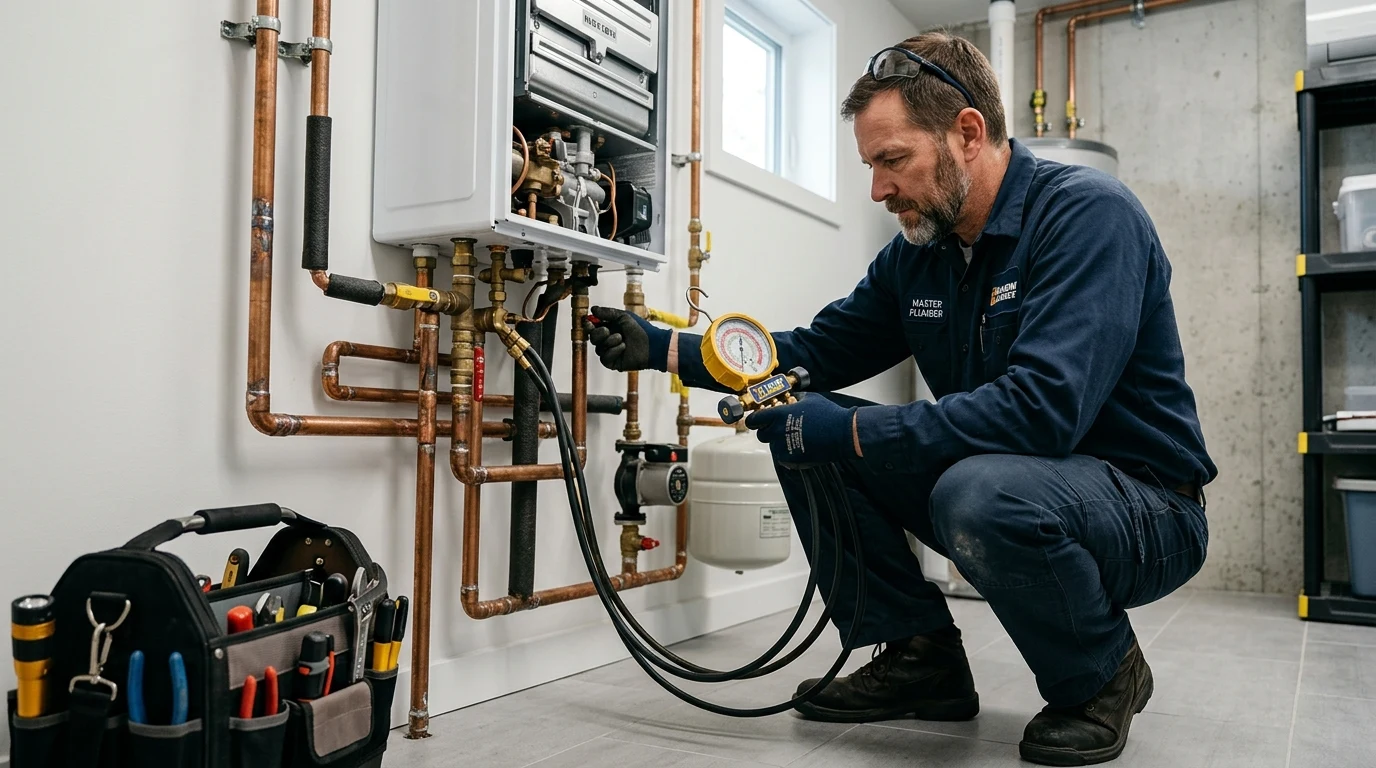
The thermal engine driving modern hydronic systems is the wall-hung condensing combination boiler (combi boiler) from premium manufacturers such as Navien (NPE/NCB series), Viessmann, Lochinvar, or Weil-McLain. Condensing combi boilers achieve Annual Fuel Utilization Efficiency (AFUE) ratings between 95% and 98% by extracting latent heat of vaporization from the combustion flue gases.
The Physics of Primary / Secondary Pumping (Hydraulic Decoupling)
In hydronic design, connecting high-flow radiant zone circulators directly across a modern condensing boiler is a catastrophic design error. Modern compact boilers contain miniature stainless-steel heat exchangers with extremely high internal frictional resistance (often 10 to 15 feet of head loss at 8 GPM). If multiple zone valves open simultaneously, the zone pumps can fight the boiler internal pump, causing thermal shock, cavitation, and boiler shutdown.
To prevent pump interference, engineers install a Primary/Secondary Piping Loop connected via closely spaced tees (spaced no more than 4 pipe diameters apart, center-to-center) or an engineered Hydraulic Separator (Low Loss Header):
- Primary Loop (Boiler Circuit): The boiler pump circulates hot water exclusively through the boiler and the hydraulic separator at a constant, factory-engineered flow rate, guaranteeing maximum condensing heat transfer.
- Secondary Loop (Radiant Distribution): Secondary variable-speed circulator pumps draw hot water from the hydraulic separator and distribute it through the floor loops at whatever variable flow rate the individual zone thermostats dictate, completely isolated from the boiler’s internal hydraulics.
5. Critical Closed-Loop Mechanical Components
A closed hydronic system requires several specialized mechanical safety and operational devices operating in continuous harmony:
| Component | Mechanical Purpose | Operating Setpoint / Standard | Failure Symptoms |
|---|---|---|---|
| Diaphragm Expansion Tank | Absorbs thermal expansion volume of water as it heats | Pre-charged to 12 PSI air pressure | Pressure spikes to 30 PSI; relief valve discharges water |
| Microbubble Air Separator (Spirovent) | Coalesces and vents entrained microscopic air bubbles from water | Continuous mechanical venting | Gurgling pipe noise; air-bound loops; cold floor zones |
| Thermostatic Mixing Valve (TMV) | Blends 160°F boiler water down to safe 90°F–115°F floor temps | ASSE 1017 Certified | Floor overheating; warping of hardwood; cracked tile grout |
| Backflow Preventer & Auto-Fill PRV | Isolates non-potable boiler loop; maintains 12–15 PSI cold fill | ASSE 1012 / Dual Check with Vent | Boiler low-water cutoff error; glycol backflow into tap |
| Magnetic Dirt Separator (Fernox/Adey) | Neodymium magnet extracts black magnetite (iron oxide) particles | Full-flow bypass filtration | Circulator pump rotor seizure; plugged heat exchanger |
6. Colorado Freeze Protection: Inhibited Propylene Glycol Formulation
In Front Range regions, power outages caused by heavy winter wet snowstorms or extreme polar vortex chills can subject residential plumbing to sub-zero temperatures. If a hydronic heating loop filled with pure water freezes, the 9% volumetric expansion of freezing ice will split PEX fittings, burst boiler heat exchangers, and crack cast iron pumps, resulting in tens of thousands of dollars in catastrophic water damage upon thawing.
To provide fail-safe freeze protection, hydronic heating loops serving garages, snowmelt driveways, sunrooms, or vacation homes are filled with an engineered solution of virgin inhibited propylene glycol:
- Propylene Glycol vs. Ethylene Glycol: Automobile antifreeze (ethylene glycol) is strictly illegal in residential hydronics due to its extreme toxicity to humans and pets. Plumbing codes strictly mandate non-toxic USP food-grade propylene glycol.
- Freeze Protection Concentration Sizing: In Broomfield and Denver metro, systems are dosed with a 30% to 35% glycol concentration by volume, providing burst protection down to -20°F (-29°C). Higher concentrations (e.g., 50%) are deployed for outdoor driveway snowmelt loops.
- Industrial Corrosion Inhibitors: Raw glycol naturally breaks down over time under thermal cycling into organic glycolic and formic acids, driving fluid pH down into corrosive ranges (pH < 7.0). Quality hydronic glycol (such as Cryo-Tek or Fernox Alphi-11) incorporates alkaline chemical buffer inhibitors that maintain fluid pH between 8.0 and 9.5, protecting aluminum, copper, and cast iron. Glycol freeze point and pH must be tested annually using a professional optical refractometer and chemical test strips.
7. Thermal Imaging Diagnostics: Precision Infrared Balancing
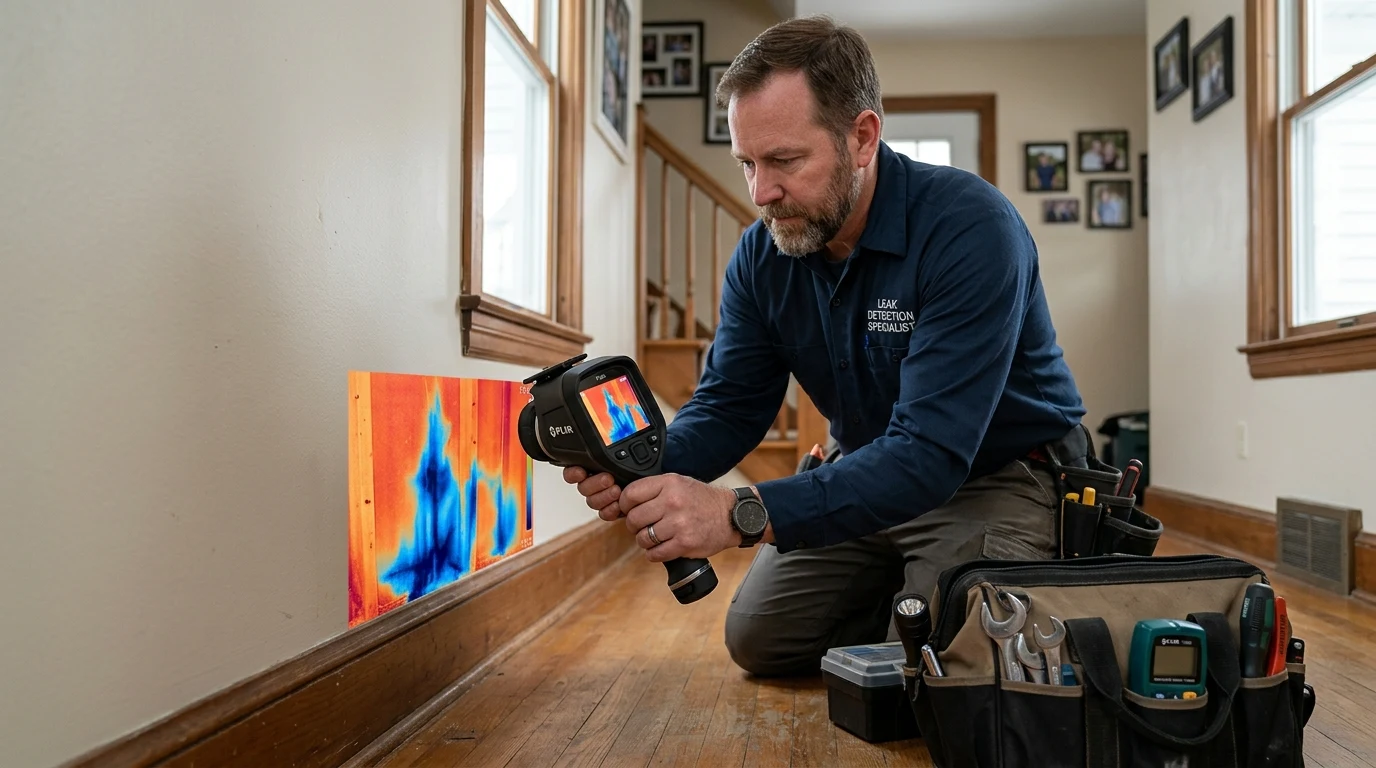
Because hydronic radiant tubing is completely concealed beneath concrete slabs or finished flooring, troubleshooting cold zones or uneven heating historically required guesswork. Today, certified hydronic plumbing technicians deploy high-resolution FLIR radiometric thermal imaging cameras to visualize real-time heat transfer physics.
What Thermal Imaging Reveals:
- Air-Bound Loop Locks: An individual radiant loop that has air bubbles trapped in an apex will show zero thermal signature on the infrared camera, remaining a stark blue-purple channel against the warm orange-yellow active loops.
- Thermal Bridging & Subfloor Gaps: Areas where insulation board was improperly seated or subfloor heat-transfer plates have detached from the subfloor show up immediately as cool dead zones.
- Micro-Leaks Under Slabs: A pressurized leak in an in-slab radiant loop produces a characteristic expanding thermal bloom—a fuzzy, hot halo spreading outward through the concrete beyond the defined line of the tubing.
8. Heat Loss Engineering: Manual J Calculations & Surface Temperature Limits
Hydronic radiant floor design begins with an accurate room-by-room Manual J heat loss calculation. At Colorado’s Front Range design temperature (-1°F outdoor dry bulb), every square foot of building envelope loses heat to the outdoor atmosphere through conduction and air infiltration.
The required floor heat flux ($q$) in BTU/hr per square foot is calculated as:
q = frac{text{Total Room Heat Loss (BTU/hr)}}{text{Active Net Floor Area (sq ft)}}
Typical modern well-insulated Front Range homes require 18 to 28 BTU/hr·sq ft, while older, drafty ranch homes with single-pane windows can demand 35 to 45 BTU/hr·sq ft.
Flooring R-Value & Temperature Limits
Floor coverings have thermal resistance (R-value). Ceramic tile and polished concrete are ideal (R-value 0.25 to 0.50), transferring heat with minimal water temperature requirements (95°F–105°F). Hardwood flooring (R-value 1.0 to 1.5) requires higher water supply temperatures (115°F–125°F), but hardwood industry standards (NWFA) strictly mandate that finished floor surface temperature must never exceed 85°F (29.4°C) to prevent the wood from drying, cupping, or splitting. Thick carpet with dense foam padding (R-value > 2.5) acts as an insulator that chokes radiant heat transfer and is generally discouraged in hydronic applications.
9. Step-by-Step Air Purging & System Commissioning Protocol
Air is the number-one enemy of hydronic heating. Even microscopic air pockets will cause circulator pumps to dead-head and freeze floor loops. Follow this professional commissioning sequence:
- Isolate All Zones: Close every branch isolation valve on the radiant manifold return rail, leaving only Loop #1 open.
- Connect High-Pressure Purge Rig: Connect a high-pressure municipal water hose to the manifold supply purge port, and run a heavy-duty garden hose from the manifold return drain port into a utility sink or floor drain. Submerge the discharge hose end in a bucket of water.
- High-Velocity Flush: Open the purge supply full bore, forcing at least 3.5 to 5.0 GPM through Loop #1. High velocity is mandatory to exceed the 2.0 fps air-entrainment threshold and sweep stubborn air bubbles out of ceiling drops. Continue flushing until bubbles stop emerging in the bucket and water discharges crystal clear.
- Sequential Loop Purging: Close Loop #1 and open Loop #2. Repeat the high-velocity purge sequentially for every loop on the manifold.
- Pressurize & Reconnect: Reopen all loops, disconnect purge hoses, and use the automated pressure-reducing fill valve to bring the closed system to 12 to 15 PSI static cold pressure.
10. Radiant Subfloor Installation Methods: Slab-on-Grade vs. Gypsum vs. Heat Plates
Hydronic radiant floor systems must be tailored to the structural framing and architectural profile of the residence. In Colorado construction, three distinct mechanical delivery methods are utilized:
1. Embedded Concrete Slab-on-Grade (Thermal Mass Storage)
Commonly deployed in finished basements, walkouts, and modern slab-on-grade custom homes. Continuous 1/2-inch PEX-a loops are tied directly to welded wire rebar mesh or snapped into molded polystyrene insulation panels before pouring 4 to 5 inches of structural concrete.
- Thermal Flywheel Effect: The dense concrete slab acts as an immense thermal capacitor, soaking up heat and continuing to radiate warmth for 6 to 10 hours after the boiler shuts off. This provides bulletproof comfort during sub-zero cold snaps.
- Mandatory Sub-Slab Insulation: Under Colorado Energy Conservation Code (IECC), slabs must be underlaid with a minimum of R-10 to R-15 extruded polystyrene (XPS) rigid foam insulation. Without continuous sub-slab insulation, up to 35% of the thermal energy will be conducted downward into the frozen subsoil, wasting thousands of therms of natural gas.
2. Thin Gypsum Thermal Underlayment (Maxxon Gyp-Crete)
For upper-story wood frame construction or remodeling, PEX tubing is fastened directly to the plywood subfloor, and a specialized 1-1/2-inch layer of self-leveling gypsum-based concrete (such as Gyp-Crete or Therma-Floor) is poured over the tubes.
- Advantages: Provides a dead-flat, fire-rated, acoustically dampened thermal mass that responds much faster to thermostat changes than a thick structural slab (reaching setpoint within 1 to 2 hours), while weighing only 13 to 15 lbs per square foot—well within standard floor joist structural load limits.
3. Under-Floor Joist Staple-Up with Aluminum Heat Transfer Plates
When remodeling existing finished rooms without altering existing hardwood or tile floors, PEX tubing can be installed from the unfinished basement or crawlspace beneath the floor joists. Heavy-gauge extruded aluminum heat transfer plates (0.040″ to 0.060″ thick) are screwed tightly to the underside of the subfloor.
- Thermal Conduction Mechanics: Because wood has low thermal conductivity, the high-conductivity aluminum plates act as thermal spreaders, conducting heat from the PEX tubing across the entire width of the joist cavity to provide even floor warmth. The joist cavity below must be tightly sealed and packed with minimum R-19 fiberglass or rockwool batts to reflect heat upward.
11. Outdoor Snowmelt Hydronics: Front Range Driveway & Walkway Engineering
Colorado’s intense spring snowfalls regularly dump 12 to 24 inches of heavy, wet “heart attack” snow in Broomfield and mountain foothills. Many luxury homeowners and commercial facilities deploy outdoor hydronic snowmelt systems to keep driveways, steep access ramps, and flagstone walkways completely free of snow and black ice without salt or snowplowing.
Hydronic snowmelt is governed by ASHRAE Snow Melting Standards, categorized into three performance tiers:
- Class I (Residential Walkways & Driveways): Designed to melt snow at an average rate of 0.5 to 1.0 inch per hour during a typical snowfall. Requires a boiler design capacity of 100 to 150 BTU/hr per square foot.
- Class II (Commercial Sidewalks & Hospital Steps): Designed for 100% snow clearance during snowfall, preventing any slush accumulation. Sized at 150 to 200 BTU/hr per square foot.
- Class III (Emergency Vehicle Access & Helipads): Instant snow vaporization. Sized at 250+ BTU/hr per square foot.
Automated Snowmelt Controls & Sensors
Modern snowmelt arrays do not run continuously. An automated electronic snow controller (such as a tekmar 654) monitors an in-slab optical precipitation sensor and ambient air thermistor. When ambient temperature drops below 36°F and active snow falls on the sensor head, an internal heater melts the flake; the liquid water bridges an electronic micro-grid, signaling the boiler and snowmelt circulators to fire instantly, bringing the concrete slab surface to a dry 38°F before ice can bond to the pavement.
12. Circulator Pump Hydraulics: Darcy-Weisbach & Head Loss Calculations
Selecting the correct circulator pump requires matching the pump’s mechanical performance curve to the system hydraulic head loss. If a pump is undersized, water velocity through the PEX loops will drop below the laminar threshold, causing extreme temperature differentials (ΔT > 25°F) and cold floor zones. Conversely, an oversized pump creates high fluid velocity that causes erosion corrosion in copper headers and wastes excessive electrical power.
Plumbing engineers determine required flow rate ($GPM$) and head loss using foundational fluid mechanics:
text{Flow Rate (GPM)} = frac{text{Total Zone Heat Load (BTU/hr)}}{500 times Delta T}
For a radiant floor zone delivering 40,000 BTU/hr with an engineered 15°F temperature drop between supply and return:
GPM = frac{40,000}{500 times 15} = frac{40,000}{7,500} = mathbf{5.33text{ GPM}}
The frictional head loss across the longest PEX loop, distribution manifold, and mechanical room piping is calculated using the Darcy-Weisbach equation for smooth polymer tubing. For standard 1/2″ PEX at 0.75 GPM per loop, head loss is approximately 2.8 feet of head per 100 feet of tubing. Adding fitting allowances, an ECM variable-speed circulator (such as a Grundfos ALPHA2 or Taco 0018e) operating in constant-pressure or auto-adapt mode automatically throttles its wattage from 45W down to 5W as zone valves open and close, maximizing electrical efficiency.
13. Hydronic Snowmelt Slab Construction: Concrete Chemistry & Expansion Joints
Pouring a structural concrete driveway or patio embedded with high-temperature hydronic snowmelt loops presents severe structural engineering challenges. As the snowmelt system cycles between sub-zero ambient conditions and 120°F supply fluid, the immense thermal expansion coefficient of concrete creates internal shear stresses that can crack slabs if not engineered with precision expansion joints and crack-control reinforcement.
Structural Placement Rules for Snowmelt PEX
- Depth of Embedment: PEX-a snowmelt tubing must be positioned between 2.0 and 3.0 inches below the finished concrete surface. Placing tubing too deep (e.g., at the bottom of a 6-inch slab) dramatically increases thermal response time, requiring hours of pre-heating before snow can be melted. Placing tubing too shallow (< 1.5 inches) creates surface spalling and micro-cracking directly above the tubing runs.
- Control Joint Penetration Sleeves: Saw-cut contraction joints and tooled expansion joints are designed to crack through the full depth of the concrete. PEX tubing crossing any expansion or contraction joint must be protected by a minimum 12-inch to 18-inch flexible polyethylene or PVC protective sleeve centered over the joint. This sleeve allows the tubing to flex and slide axially as the concrete slab expands and contracts across the joint plane without pinching or shearing the PEX pipe.
- Concrete Mix Design: The concrete mix should specify a minimum compressive strength of 4,000 to 4,500 PSI at 28 days with an air-entrainment admixture of 5% to 7%. Air-entrainment voids provide microscopic expansion relief chambers for freezing surface moisture, preventing freeze-thaw surface spalling and deicer scaling.
14. Boiler Water Demineralization & Chemical Conditioning (VDI 2035 Standards)
Modern condensing combi boilers incorporate ultra-compact aluminum-silicon (Al-Si) or 316L stainless-steel heat exchangers with extremely narrow internal water channels (less than 1.5 mm in cross-section). In Front Range Colorado, filling a boiler system with untreated municipal tap water containing 10 GPG hardness introduces approximately 1.5 to 2.5 pounds of dissolved calcium carbonate into the system.
When the boiler fires, this scale instantly plates out on the hottest interior surfaces of the heat exchanger tubes. Because aluminum and stainless steel expand at different rates than mineral scale, the scale causes localized hot spots, thermal stress fractures, and premature heat exchanger burnout.
To preserve boiler warranty coverage, leading manufacturers (including Viessmann, Lochinvar, and Navien) mandate adherence to European VDI 2035 water quality standards:
- Demineralized Water Fill: Boilers must be filled with demineralized or reverse-osmosis water with total dissolved solids (TDS) below 30 PPM and water hardness below 0.5 GPG (8.5 mg/L).
- Strict pH Control: For aluminum heat exchangers, system fluid pH must be rigorously maintained between 8.2 and 8.5. A pH above 9.0 or below 7.5 will chemically dissolve the protective oxide layer of the aluminum casting. For stainless-steel boilers, a pH between 8.0 and 9.5 is required.
- Corrosion Inhibitor Dosing: The system must be charged with an engineered molybdate or organic polymer corrosion inhibitor (such as Fernox F1 Protector or Sentinel X100) that forms a monomolecular barrier across all internal metallic surfaces.
15. Frequently Asked Questions (FAQ)
How much energy does hydronic radiant floor heating save compared to a furnace?
According to the U.S. Department of Energy, hydronic radiant floor systems paired with high-efficiency condensing boilers save between 25% and 40% on heating energy compared to standard forced-air systems. Savings stem from zero ductwork heat losses (forced-air ducts lose 15%–30% of energy through duct leakage in unconditioned attics/crawlspaces), direct infrared radiant absorption allowing lower thermostat settings, and condensing boiler operation in ultra-efficient low-temperature condensing mode.
Can radiant floor heating be installed beneath engineered or solid hardwood floors?
Yes, absolutely. Engineered hardwood is particularly well-suited for radiant heating because its multi-ply cross-grain construction makes it dimensionally stable against humidity fluctuations. Solid hardwood can also be used if acclimated properly and floor surface temperatures are strictly regulated below 85°F using an automated outdoor reset controller and floor slab temperature sensors.
Why are some rooms or loops cold while other rooms are warm?
Cold spots or uneven heating typically point to one of three mechanical faults: (1) hydraulic flow imbalance across the manifold, where short loops starve long loops; (2) trapped air locks in the cold loop that prevent circulator pumps from moving fluid; or (3) a seized electro-thermal zone actuator head that is stuck closed on the manifold return rail. A technician balances flows using the manifold sight-glass flow meters and purges trapped air pockets.
What happens if someone accidentally drives a nail or screw into a radiant PEX tube?
If a carpet tack strip or flooring nail pierces a radiant PEX tube, the boiler pressure will drop to zero and water will slowly weep through the subfloor. Fortunately, the loop does not need to be abandoned. A plumbing technician precisely pinpoints the puncture location using thermal imaging, carefully chips a small 4-inch access window in the concrete or subfloor, cuts the damaged section, and installs a permanent brass PEX-a expansion coupling or stainless-steel press sleeve certified for direct concrete burial.
How often does boiler hydronic heating water need to be serviced or flushed?
Unlike domestic tap water, closed-loop boiler water should not be frequently drained or refilled. Every time fresh municipal water is introduced into a boiler, fresh dissolved oxygen and mineral hardness enter the system, accelerating internal corrosion and scaling. Professional maintenance should occur annually, focusing on cleaning the magnetic dirt separator, testing glycol freeze point and pH levels, inspecting expansion tank air pre-charge, and servicing the boiler burner and condensate trap.
Can a single combi boiler handle both radiant in-floor heating and domestic hot water?
Yes, that is the engineered beauty of a combination (combi) boiler. A modern unit (like a Navien NCB-240H) incorporates an internal motorized 3-way diverter valve and an ultra-high-surface-area brazed plate heat exchanger. Under normal operation, it circulates warm water through your radiant floor loops. The moment someone opens a hot shower or faucet, the boiler instantly prioritizes domestic hot water, routing 100% of its burner power (up to 199,000 BTU) to deliver endless on-demand domestic hot water.
What is an outdoor reset control curve and why is it essential in Colorado?
An outdoor reset control continuously measures outdoor air temperature via an exterior sensor mounted on the north foundation wall. When outdoor temperatures are mild (e.g., 45°F), the controller automatically lowers boiler water supply temperature to 90°F, keeping the boiler running in high-efficiency condensing mode. When an arctic front drops temperatures to -10°F, the controller automatically scales supply water up to 130°F, perfectly matching boiler heat output to the home’s instantaneous envelope heat loss.
Can hydronic radiant systems be used for summer cooling?
While chilled water can technically be circulated through in-floor loops using a reverse-cycle hydronic heat pump, radiant floor cooling is rarely implemented in residential applications due to severe condensation risks. If the floor surface drops below the room’s dew point temperature, moisture condensates on the floor, creating dangerous slip hazards and ruining hardwood. Modern hydronic cooling is typically handled via dedicated chilled-water fan coils or ductless mini-splits.
Front Range Master Hydronic Heating & Combi Boiler Specialists
Experience the ultimate in silent, energy-efficient radiant comfort. Broomfield Emergency Plumber provides precision hydronic manifold balancing, high-efficiency combi boiler installation, glycol freeze testing, and thermal imaging diagnostics throughout Broomfield and the North Metro corridor.